Image Transfer and Paper Separation
D017/D018/D019/D020 6-68 SM
1. When the CPU receives the image writing start signal, the CPU instructs the high
voltage supply board to supply +10μA (low transfer current level) to the roller. This
prevents any positively charged toner on the drum surface from transferring to the
transfer roller.
2. At a certain time after the low transfer current has been supplied to the roller, an
appropriate current is applied to the roller to transfer the toner to the paper.
3. After the trailing edge of the paper has passed through the roller, transfer current turns
off. In multiple copy mode, the transfer current shifts again to the low transfer current.
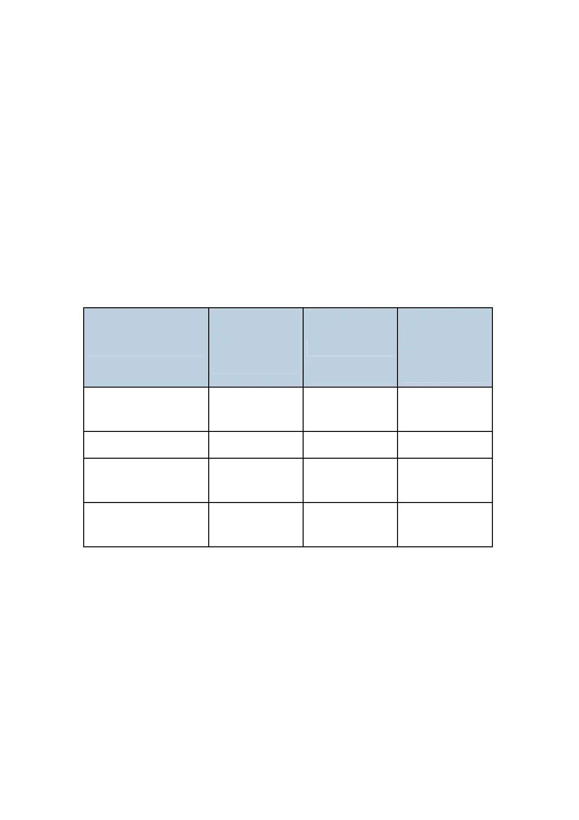
The transfer current (high transfer current level) depends on the paper feed station, paper
width, and the temperature in the machine.
Example: Temperature = 15 °C to 24 °C
Paper Width
Paper Tray /
By-pass Tray
(Normal)
Duplex (2nd Side)
By-pass Tray
(Thick) / 2nd
Paper Tray
(Special Paper)
A3/11” x 17”,
A4/8.5 x 11”sideways
14μA 10μA 14μA
B4
13μA 12μA 15μA
A4/11” x 8.5 lengthwise,
A5/5.5 x 8.5 sidewise
13μA 16μA 17μA
A5/8.5 x 5.5 lengthwise
and less
16μA 16μA 20μA
The transfer current can be adjusted using SP2301, except for the low transfer current.
Be careful when increasing the transfer current. This might cause a ghosting effect, in
which part of the image at the top of the page is repeated lower down the page at a lower
density. It may also damage the OPC drum in the worst case.
6.12.3 TRANSFER ROLLER CLEANING
If the paper size is smaller than the image, or if a paper jam occurs during printing, toner
may be transferred to the roller surface. To prevent the toner from transferring to the back
side of the printouts, the transfer roller requires cleaning before the next printing run.
During transfer roller cleaning, the high voltage supply unit supplies a negative cleaning
 Loading...