Home
Ricoh
All in One Printer
MET-C1
Ricoh MET-C1 User Manual
4
of 1
of 1 rating
688 pages
Give review
Manual
Specs
To Next Page
To Next Page
To Previous Page
To Previous Page
Loading...
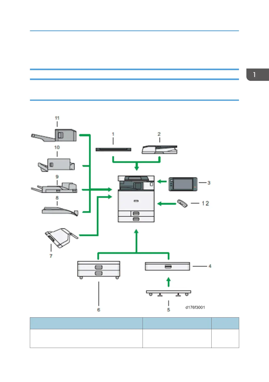
Machine Codes and Peripherals Configuration
Diagram
Options
Mainframe: ARDF as standard (NA, EU)
Item
Machine Code
Call out
Platen Cover PN 2000
D700 (EU, Asia, TWN, CHN,
KOR)
1
Machine Codes and Peripherals Configuration
39
40
42
Table of Contents
Table of Contents
7
Important Safety Notices
3
Prevention of Physical Injury
3
Health Safety Conditions
3
Observance of Electrical Safety Standards
3
Safety and Ecological Notes for Disposal
4
Laser Safety
4
Warnings, Cautions, Notes
4
Symbols, Abbreviations and Trademarks
6
Trademarks
6
Table of Contents
7
1 Product Information
23
Product Overview
23
Component Layout
23
Scanner Unit
24
Laser Exposure Unit
25
Image Transfer Unit
26
Pcdu
27
Toner Supply / Waste Toner Bottle
28
Paper Feed Unit
29
Duplex Unit
30
By-Pass Unit
31
Fusing Unit
32
Paper Transfer / Paper Exit
33
Air Flow
34
Drive Unit
35
Paper Feed Unit PB3150 (D694)
35
Paper Feed Unit PB3210 (D787)
35
Board / Switch
36
Paper Path
37
Drive Layout
39
Machine Codes and Peripherals Configuration
41
Diagram
41
Options
41
Specifications
45
Guidance for those Who Are Familiar with Similar Products
46
Differences from Similar Models
46
Scan, LD Unit, Paper Feed Unit
46
Duplex, Driving, Main Frame
46
Pcdu
47
Fusing
48
Electrical Component
48
New Features of D176/D177
48
Important Notice for Machine
49
2 Installation
51
Installation Requirements
51
Environment
51
Machine Space Requirements
52
Machine Dimensions
53
Power Requirements
53
Input Voltage Level
54
Main Machine Installation
55
Important Notice on Security Issues
55
Overview
55
Password Setting Procedure
56
Installation Flow Chart
61
Accessory Check
61
Installation Procedure
63
Removal of Packing Materials and Shipping Retainers / Removal of PCDU Seal
63
Toner Bottle Installation
68
Attaching the Optical Cloth Pocket
69
Attaching Paper Output Tray Parts
70
Connecting the Power Cord
70
Image Quality Test / Settings
71
Image Quality Test
71
Checking the Copy Image with the Test Chart
71
Paper Setting
71
Moving the Machine
71
Paper Feed Unit PB3210
73
Accessory Check
73
Installation Procedure
73
Paper Feed Unit PB3150
77
Accessory Check
77
Installation Procedure
77
Caster Table Type M3
81
Accessory Check
81
Installation Procedure
81
How to Place MFP on the Caster Table
82
How to Place the Paper Feed Unit PB3150 on the Caster Table
82
Platen Cover PN2000
84
Accessory Check
84
Installation Procedure
84
Ardf Df3090
87
Accessory Check
87
Installation Procedure
87
When Feeding Thin Paper
92
Bin Tray BN3110
93
Accessory Check
93
Installation Procedure
93
Internal Shift Tray SH3070
101
Accessory Check
101
Installation Procedure
101
Side Tray Type M3
106
Accessory Check
106
Installation Procedure
107
Internal Finisher SR3130
111
Accessory Check
111
Installation Procedure
111
Punch Unit PU3040
122
Accessory Check
122
Installation Procedure
123
Internal Finisher SR3180
130
Accessory Check
130
Installation Procedure
131
Staple Setting as an Initial Setting
142
Anti-Condensation Heater
144
Anti-Condensation Heater (Scanner)
144
Accessory Check
144
Installation Procedure
145
Anti-Condensation Heater (PCDU)
150
Accessory Check
150
Installation Procedure
151
Key Counter Bracket Type M3
157
Accessory Check
157
Installation Procedure
157
Optional Counter Interface Unit Type a
160
Accessory Check
160
Installation Procedure
160
Key Counter
160
Smart Card Reader Built-In Unit Type M2 (D739-36)
162
Accessory Check
162
Installation Procedure
162
Imageable Area Extension Unit Type M3
168
Accessory Check
168
Installation Procedure
168
When You Forgot to Change the SP
169
Internal Options
170
List of Slots
170
IEEE 802.11A/G/N Interface Unit Type M2
172
Accessory Check
172
Installation Procedure
172
Attaching the Boards
173
Attaching the Antenna
173
Settings
174
Check the Connection of the Wireless LAN Interface
174
IEEE 1284 Interface Board Type a
176
Accessory Check
176
Installation Procedure
176
File Format Converter Type E
178
Accessory Check
178
Installation Procedure
178
Copy Data Security Unit Type G
180
Accessory Check
180
Installation Procedure
180
Settings (to be Done by the User)
181
Equipment Administrator Settings
181
Bluetooth Interface Unit Type D
182
Accessory Check
182
Installation Procedure
182
SD Card Option
184
SD Card Slots
184
List of Slots Used
184
SD Card Appli Move
186
Overview
186
Move Exec
187
Undo Exec
189
Data Overwrite Security Unit Type H (D377)
191
Overview
191
Component List
191
Before You Begin the Procedure
191
Seal Check and Removal
192
Installation Procedure
193
Camera Direct Print Card Type M3
194
Accessory Check
194
Installation Procedure
194
Browser Unit Type M9
196
Accessory Check
196
Installation Procedure
196
Settings
198
Browser Default Setting
198
SD Card for Netware Printing Type M3
199
Accessory Check
199
Installation Procedure
199
OCR Unit Type M2
201
Accessory Check
201
Searchable PDF Function Outline
201
Installation Procedure
201
Postscript3 Unit Type M3
204
Accessory Check
204
Installation Procedure
204
Security Function Installation
206
Data Overwrite Security
207
Before You Begin the Procedure
207
Installation Procedure
207
HDD Encryption
208
Before You Begin the Procedure
208
Enable Encryption Setting
209
Check the Encryption Settings
212
Print the Encryption Key
213
Memory Unit Type M3 2GB
215
Accessory Check
215
Installation Procedure
215
3 Preventive Maintenance
217
PM Parts Settings
217
Replacement Procedure of the PM Parts
217
After Installing the New PM Parts
218
Preparation before Operation Check
218
Operation Check
219
4 Replacement and Adjustment
221
Notes on the Main Power Switch
221
Push Switch
221
Characteristics of the Push Switch (DC Switch)
221
Shutdown Method
222
Forced Shutdown
222
Beforehand
224
Special Tools
225
Exterior Covers
226
Front Cover
226
Controller Cover
228
Upper Left Cover
228
Left Rear Cover
229
Left Cover
229
Rear Cover
232
Rear Right Cover
233
Rear Lower Cover
233
Scanner Rear Cover
234
Scanner Rear Cover (Small)
234
Right Rear Cover
234
Right Upper Cover
235
Main Power Switch Cover
236
Waste Toner Cover
236
Reverse Tray
237
Paper Exit Tray
238
Paper Exit Cover
238
Paper Exit Lower Cover
238
Paper Exit Front Cover
239
Inner Upper Cover
240
Inner Lower Cover
241
Operation Panel Unit
242
Operation Panel
242
Board a
243
Board B
245
Board C
246
LCD Panel
246
Lcd
247
Notes When Replacing the LCD
247
Replacement Procedure
250
Scanner Unit
252
Scanner Exterior
252
Scanner Upper Cover
252
Scanner Right Cover
252
Scanner Front Cover
253
Scanner Left Cover
253
Exposure Glass
254
Exposure Lamp (LED)
256
Scanner Motor
257
Lens Block
260
Original Size Sensor
260
Sio
261
Scanner HP Sensor
262
DF Position Sensor
263
Adjusting the Scanner Wire
264
Scanner Wire (Front)
264
Scanner Wire Assembly (Front Side)
267
Scanner Position Adjustment
269
Scanner Wire (Rear)
270
Scanner Wire Assembly (Rear Side)
273
Modifying the Scanner (Contact/Contactless) When Using ARDF
274
Procedure for the ADF
274
Procedure for the Scanner
277
Laser Unit
278
Before Replacement
279
Removing
279
Installing a New Laser Unit
280
Adjustment after Replacing the Laser Unit
281
Polygon Motor
282
Adjustment after Replacing the Polygon Motor
282
Pcdu
283
Before Replacing the PCDU
283
Replacement
283
Pcu/Development Unit
285
Before Replacing a PCU
285
Before Replacing a Development Unit
287
Replacement
287
Notes for Assembling Pcu/Development Unit
290
Method for Checking after Replacement
290
Imaging Temperature Sensor (Thermistor)
291
Waste Toner
293
Replacement
293
Adjustment after Replacing
293
Image Transfer Unit
295
Image Transfer Belt Unit
295
Adjustment before Replacing the Image Transfer Belt Unit
296
Replacement
296
Image Transfer Cleaning Unit
299
Adjustment before Replacing the Image Transfer Cleaning Unit
300
Replacement
300
Image Transfer Belt
303
Replacement
303
Adjustment after Replacing the Image Transfer Belt
306
Paper Transfer Roller
307
Paper Transfer Roller Unit
307
Adjustment before Replacing the Paper Transfer Roller Unit
307
Replacement
307
Fusing Entrance Sensor
309
TM (ID) Sensor
310
Before Replacing the TM(ID) Sensor
310
Replacement Procedure
312
Adjustment after Replacing the TM(ID) Sensor
313
Temperature and Humidity Sensor
314
ITB Contact and Release Sensor
315
Drive Unit
317
Overview
317
Paper Feed Motor
318
Transport Motor
318
Transfer Motor Unit
319
Imaging Drive Unit
320
PCU Motor: CMY
322
Development Motor: CMY
322
Development Solenoid
322
Fusing Motor
324
Paper Exit / Pressure Release Motor
324
Duplex Entrance Motor
325
Toner Transport Motor
326
Sub Hopper
327
Toner End Sensor
331
Toner Bottle Drive Motor
332
ID Chip
333
Transport Screw
336
Fusing Unit
342
Adjustment before Replacing the Fusing Unit
342
Replacement
342
Fusing Entrance Guide Plate
343
Replacement
343
Cleaning the Fusing Entrance Guide Plate
344
Fusing Exit Guide Plate
344
Replacement
344
Cleaning the Fusing Exit Guide Plate
345
Fusing Upper Cover
346
Fusing Lower Cover
346
Fusing Front Cover
347
Fusing Rear Cover
348
Heating Sleeve Unit
349
Replacement
349
How to Cancel SC544-02/SC554-02 with a New Unit Detection Fuse
352
Pressure Roller
353
Adjustment before Replacing the Pressure Roller
353
Replacement
353
Thermostat Unit
355
Non-Contact Thermistor Unit
356
Fusing Thermistor
357
Fusing Thermopile Unit
357
Pressure Roller HP Sensor
358
Fusing Shield Position Sensor
358
Fusing Shield Drive Motor
359
Paper Exit
361
Paper Exit Unit
361
Paper Exit Switching Solenoid
361
Paper Exit Sensor
362
Reverse Sensor
364
Reverse Motor
365
Fusing Exit Sensor
366
Paper Feed
368
Paper Feed Unit
368
1St Paper Feed Unit
368
2Nd Paper Feed Unit
369
Paper Dust Collection Unit
371
Separation Roller, Torque Limiter
372
Pick-Up Roller, Paper Feed Roller
373
1St Tray Lift Motor / 2Nd Tray Lift Motor
374
Vertical Transport Sensor
375
Limit Sensor
376
Paper End Sensor
377
Registration Sensor
378
By-Pass Tray Unit
379
By-Pass Tray
379
By-Pass Paper End Sensor
381
By-Pass Pick-Up Roller
382
By-Pass Paper Feed Roller
383
By-Pass Separation Roller
383
Torque Limiter
384
Duplex Unit
385
Duplex/By-Pass Motor
387
Duplex Entrance Sensor
389
Duplex Exit Sensor
390
Electrical Components
393
Overview
393
Printed Circuits/Parts Inside the Controller Box
393
Printed Circuits Behind the Controller Box
394
Printed Circuit/Parts Inside the Power Box
394
Printed Circuits Behind the Power Box
395
Ipu
395
Bcu
396
When Installing the New BCU
396
Replacing the NVRAM (EEPROM) on the BCU
397
Controller Board
398
Nvrams on the Controller Board
399
Hdd
403
Adjustment after Replacement
404
Imaging IOB
404
Hvp_Tts
405
PSU (AC Controller Board)
406
PSU (DC Power)
406
Paper Transport IOB
407
Hvp-Cb
408
When Removing the HVP-CB Together with Its Bracket
411
Fans/Filters
413
Odor Filter
413
Development Intake Fan/Right
413
Development Intake Fan/Left
414
Ozone Exhaust Fan
415
Paper Exit Cooling Fan
415
Fusing Exhaust Heat Fan
416
Toner Supply Cooling Fan
417
PSU Cooling Fan
418
Power Box Cooling Fan
419
Image Adjustment
420
Auto Color Calibration
420
Printer Gamma Correction
420
Copy Mode
421
Printer Mode
425
Color Registration
426
Check the Occurrence of Color Registration Errors
426
Judgment for Type of Color Registration Error
426
Adjustment after Replacing
436
Image Position Adjustment
436
Parts that Require Adjustment
436
Laser-Related Adjustment
436
Scanner-Related Adjustment
438
ADF Image Adjustment
441
5 Troubleshooting
443
Self-Diagnostic Mode
443
Service Call Codes
443
Service Call Conditions
443
SC Logging
444
SC Automatic Reboot
444
Controller Self-Diagnosis Outline
447
Controller Self-Diagnosis Flowchart
448
Service Call 101-195
452
SC100 (Engine: Scanning)
452
Service Call 201-285
459
SC200 (Engine: Image Writing)
459
Service Call 324-396
465
SC300 (Engine: Charge, Development)
465
Error SC361-01...SC370-01
467
Service Call 441-498
470
SC400 (Engine: Around the Drum)
470
Service Call 501-584
476
SC500 (Engine: Paper Transport 1: Paper Feed, Duplex, Transport)
476
Service Call 620-689
522
SC600 (Engine: Communication and Others)
522
Error SC665...SC669-13
525
SC600 (Controller)
530
Error SC636-02...SC637-01
532
Service Call 700-792
541
SC700 (Engine: Peripherals)
541
Service Call 816-899
553
SC800 (Controller)
553
Error SC816-23...51
554
Service Call 900-998
614
SC900 (Engine: Others)
614
SC900 (Controller)
615
When SC549 Is Displayed
622
Troubleshooting Flowchart
622
Fusing Shield Check
623
Solution
626
When SC670 Is Displayed
628
Troubleshooting Flowchart
628
Jam Detection
629
Jam Display
629
Sensor Locations
630
Clearing a Paper Jam
631
Paper Jam History
631
History Checking Method
631
Paper Jam Display
632
Jam Codes and Display Codes
632
Paper Size Code
636
Image Quality
637
When an Abnormal Image Is Generated
637
Roller Pitch
638
OCR Unit Type M2
639
Recovery Procedure
639
Electrical Component Defects
640
6 Environment
643
Energy Saver Modes
643
Timer Settings
644
Return to Stand-By Mode
644
Recommendation
645
Energy Save Effectiveness
645
Table of Contents
649
Specifications
651
General Specifications
651
Printer Specifications
653
Scan Specifications
654
Other Specifications
657
HDD Specifications
657
Noise Emission
658
1 Appendices:specifications
651
Supported Paper Sizes
660
Original Size Detection
660
Bypass Trays
665
Main Unit Tray, 1 bin Tray, Shit Tray, Side Tray
669
Printer Drivers
673
Software Accessories
673
Scanner and Lan Fax Drivers
674
Optional Equipment
675
Ardf Df3090 (D779)
675
Internal Finisher SR3130 (D690)
676
Internal Finisher SR3180 (D766)
677
Bin Tray BN3110 (D692)
680
Punch Unit PU3040 (D716)
680
Preventive Maintenance
683
Preventive Maintenance Items
683
Yield Parts
683
Mainframe
683
2 Appendices:preventive Maintenance Tables
683
4
Based on 1 rating
Ask a question
Give review
Questions and Answers:
Need help?
Do you have a question about the Ricoh MET-C1 and is the answer not in the manual?
Ask a question
Ricoh MET-C1 Specifications
General
Brand
Ricoh
Model
MET-C1
Category
All in One Printer
Language
English
Related product manuals
Ricoh M052
667 pages
Ricoh MT-C1
865 pages
Ricoh M 320
24 pages
Ricoh RN-MF1
162 pages
Ricoh M 2701
2 pages
Ricoh MP 161
192 pages
Ricoh MP C401
10 pages
Ricoh M C2000
24 pages
Ricoh MP 2001
156 pages
Ricoh MP 6002
1208 pages
Ricoh MP 6503
228 pages
Ricoh MP 2352
8 pages