Roche Diagnostics
Operator’s Manual · Version 3.1 E-7
Cedex Bio System 12 ISE description
Overview
Principles of operation
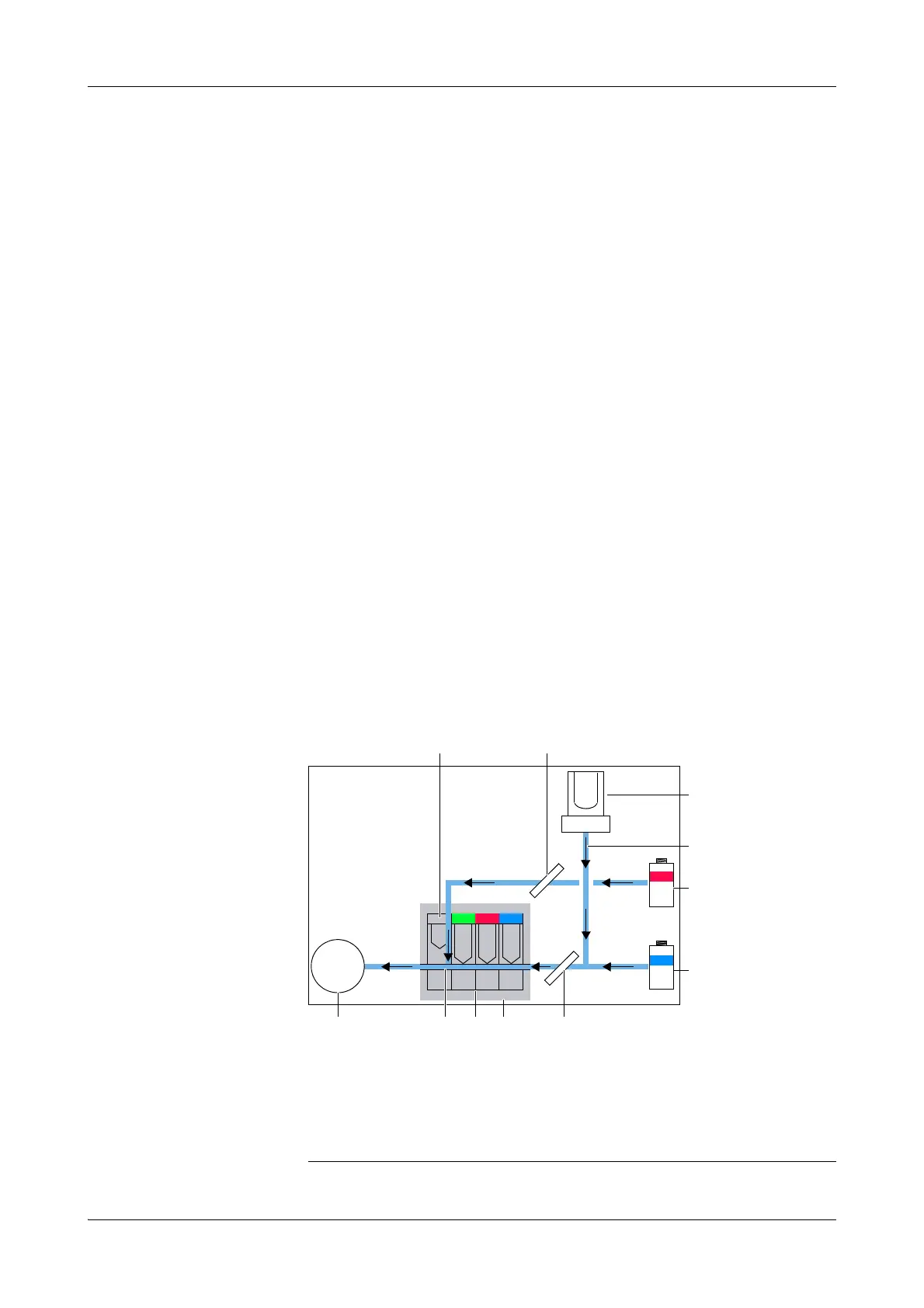
The ISE unit uses flow-through ion-selective electrodes and a reference electrode
with an open liquid junction. Each electrode has a membrane that is sensitive to a
particular type of ion.
Measuring process 1. The ISE maintenance and standard solutions (ISE Deproteinizer, ISE Etcher,
Activator, and ISE Solution 1 and 2) are pipetted from sample tubes on the
sample area to the ISE tower as required.
2. The sample is pipetted from the sample tube (located on the sample area) into the
ISE tower. The sample is diluted with system water. Mixing is performed with
four air jets arranged in a circle. These jets blow air into the tower to produce a
homogenous mixture.
3. The sample is divided into segments with the aid of a special arrangement of
valves. The first (shorter) segments are used for cleaning, these are followed by a
longer segment, on which the measurements are made.
4. The sample is passed to the ion-selective electrodes by the action of the peristaltic
pump.
The exact positioning of segments is ensured by the ISE sample sensor.
5. In the meantime, the ISE tower is washed with distilled water and dried.
6.
ISE Reference Solution is passed through the ISE Reference Electrode and into the
measuring channel downstream of the electrodes. The
ISE Reference Solution
completes the electrical circuits for each electrode so that measurements can be
made. While the measurements are made, the sample and
ISE Reference Solution
are stationary.
7. A one-point calibration is performed after each sample measurement using the
ISE Calibrator Indirect, which is located on ISE unit.
8. The electrolyte concentration of the sample is calculated.
A ISE Reference Electrode
B ISE Reference Solution sensor
C ISE tower
D Samples, controls, ISE Solution 1 and 2,
Activator, ISE Etcher, and ISE Deproteinizer
E ISE Reference Solution
F ISE Calibrator Indirect
G Peristaltic pump
H Measuring channel
I Ion-selective electrodes
J Electrode block
K ISE sample sensor
Figure E-1 Main parts of the ISE measuring system
 Loading...