13185L-002 Rev. A 1/24/06 110XiIIIPlus Maintenance Manual Page 4-33
Maintenance Section 4
Toggle Pressure
1. Ensure that the power switch is in the Off (O) position.
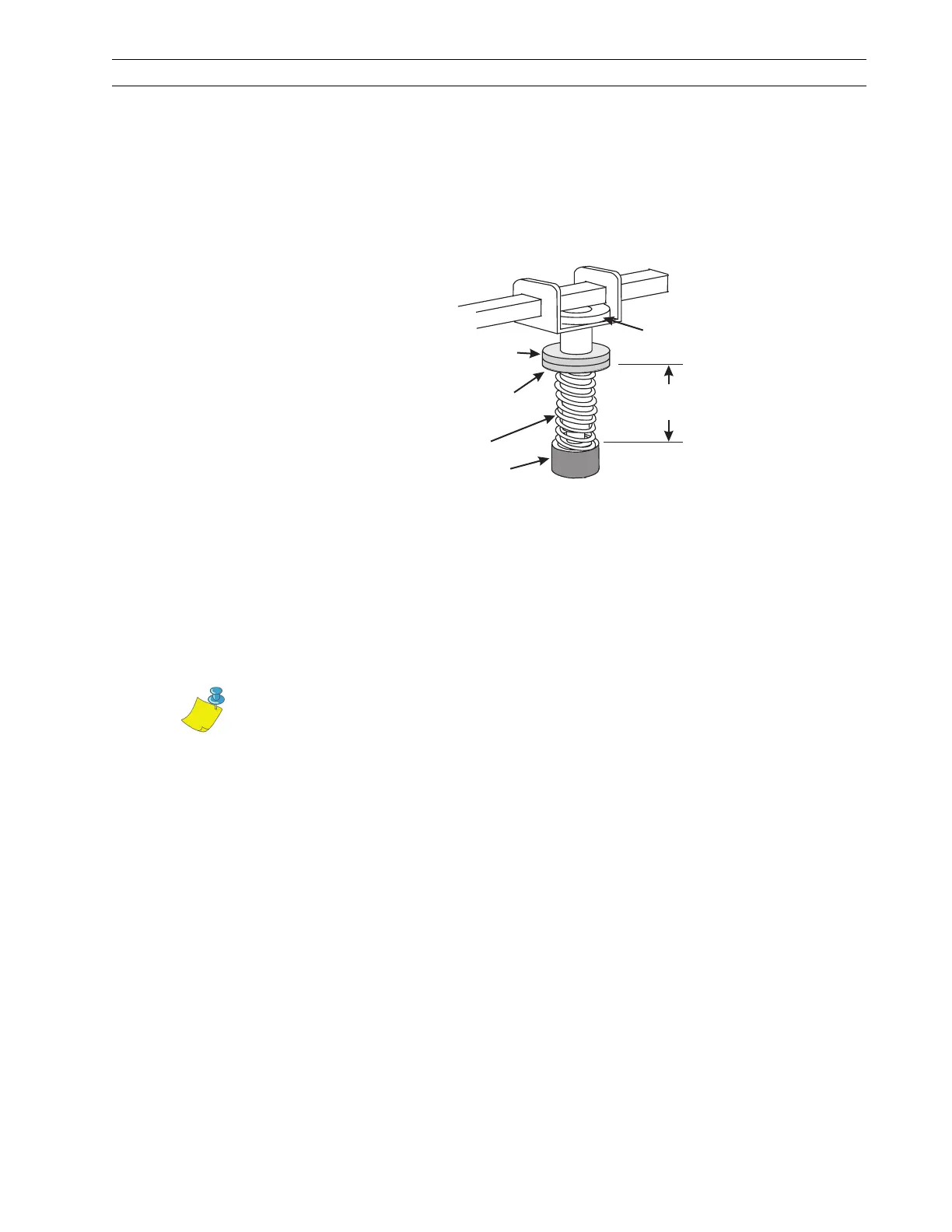
2. Refer to Figure 4-19 and measure the distance from the top of the toggle foot to the
bottom of the lower knurled nut. If the measurement is not 1-3/16 in. (30 mm),
loosen the upper knurled nut and adjust the lower knurled nut until the distance is
correct.
Figure 4-19. Initial Toggle Setting
3. Tighten the upper knurled nut against the lower knurled nut to lock that position.
4. For printers with two toggles, repeat steps 2 and 3 on the other toggle.
5. Install media and ribbon, and position the toggle in the center of the print
mechanism.
6. Perform the Pause Key Self Test by pressing and holding PAUSE while turning the
printer On (l).
7. Adjust printhead pressure for the lowest pressure that produces acceptable print
quality. Lock the toggle pressure by tightening the upper knurled nut against the
lower knurled nut.
1-3/16 in.
(30 mm)
Upper Knurled
Nut
Lower Knurled
Nut
Spring
Toggle Foot
Lock Nut
Note • To increase printhead pressure, loosen the upper knurled nut on the
toggle and adjust the lower toggle knurled nut downward. To decrease
printhead pressure, loosen the upper knurled nut and adjust the lower knurled
nut upward.
 Loading...