Page 1-12 110XiIIIPlus Maintenance Manual 13185L-002 Rev. A 1/24/06
Section 1 System Description
Communication Buffer
The size of the buffer is 5000 characters. As data is received by the processor monitors the
number of characters in the buffer. If the buffer is filled beyond 4744 characters, the Data
Terminal Ready (DTR) control leads to the off condition (negative voltage) or transmits an
XOFF (DC-3) control character to the host. When the buffer empties below 4250
characters, DTR turns on (positive voltage) or transmits an XON (DC-1) control character
to the host.
Serial Data Communication Interface Overview
The connection for this standard interface is made through the female DB-9 connector on
the rear panel. A DB-9 to DB-25 interface module is available for all RS-232 connections
through a DB-25 cable.
For all RS-232 input and output signals, the printer follows the specifications of the (EIA)
RS-232 and (CCITT) V.24.
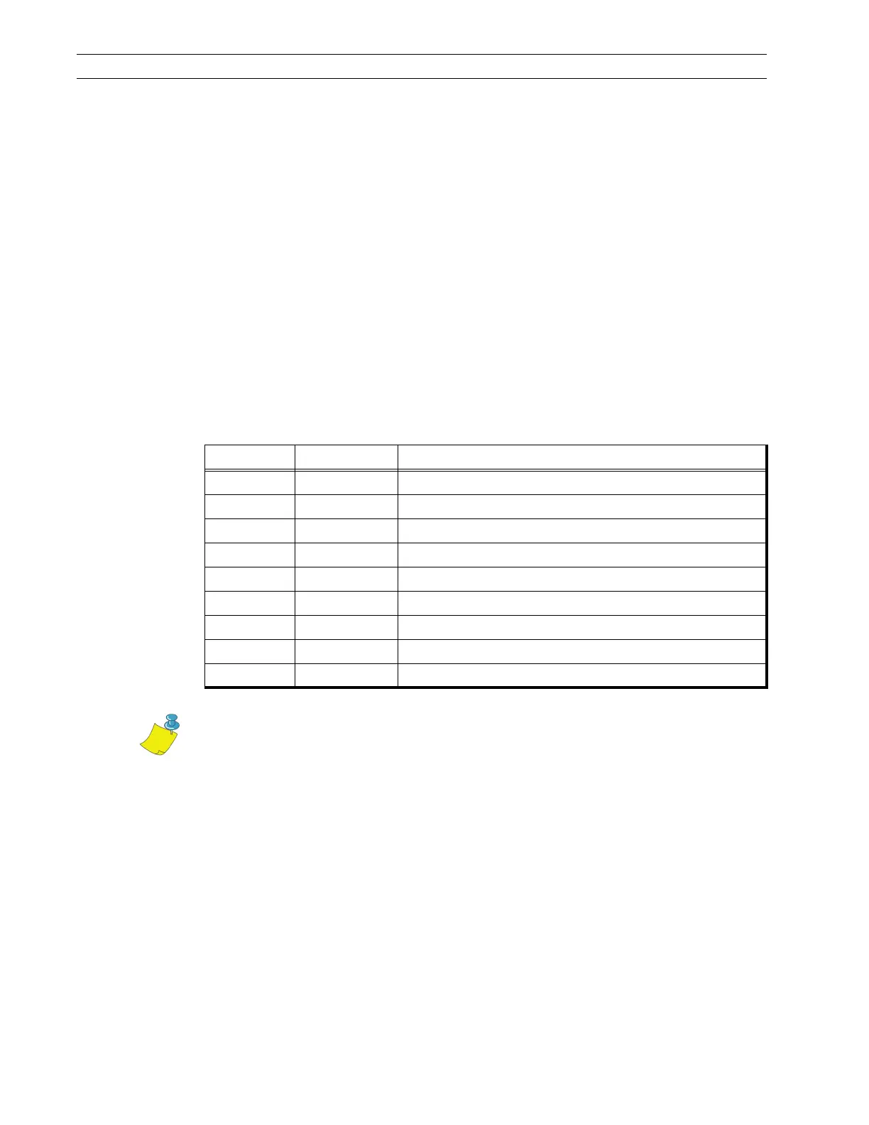
The table below shows the pin configuration and function of the rear panel serial data
connector on the printer.
Pin No. Name Description
1 — Not connected
2 RXD Receive data—data input to printer
3 TXD Transmit data—data output from printer
4 DTR Data terminal ready—output from printer
5 SG Signal ground
6 DSR Data set ready—input to printer
7 RTS Request to send—output from printer
8 CTS Clear to send—input to printer
9 +5 VDC +5 VDC signal output
Notes • Pin 9 is also available as a +5 VDC power source at 750 mA. The
maximum current draw may be limited by option configuration. To enable this
capability, a jumper on the computer’s main logic board needs to be installed on
JP1, pins 2 and 3.
An interface module is required for RS-422/RS-485 interface support.
 Loading...