13185L-002 Rev. A 1/24/06 110XiIIIPlus Maintenance Manual Page 4-121
Maintenance Section 4
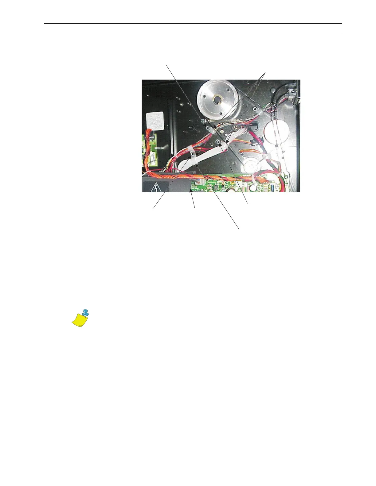
3. Refer to Figure 4-82. Remove the three nuts securing the cable clamps. Remove and
discard the one cable clamp noted in Figure 4-82.
Figure 4-82. Cable Clamps
Install the Printhead Test Option
1. Refer to Figure 4-83. Install the three spacers supplied in the kit onto the three studs
the nuts were on, leaving the three cable clamps under the spacers.
2. Route the printhead data cable as shown. Insert a cable tie through the cable clamp,
around the spacer and printhead data cable, and then tighten the cable tie.
Nut
Cable
Clamps
Nut
Power
Supply
Remove this
Cable Clamp
Nut
Note • Route the printhead data cable, as shown in Figure 4-83, is extremely
important. Lock-ups and scrambled displays may result if the printhead data
cable is routed incorrectly.
 Loading...