13185L-002 Rev. A 1/24/06 110XiIIIPlus Maintenance Manual Page 1-13
System Description Section 1
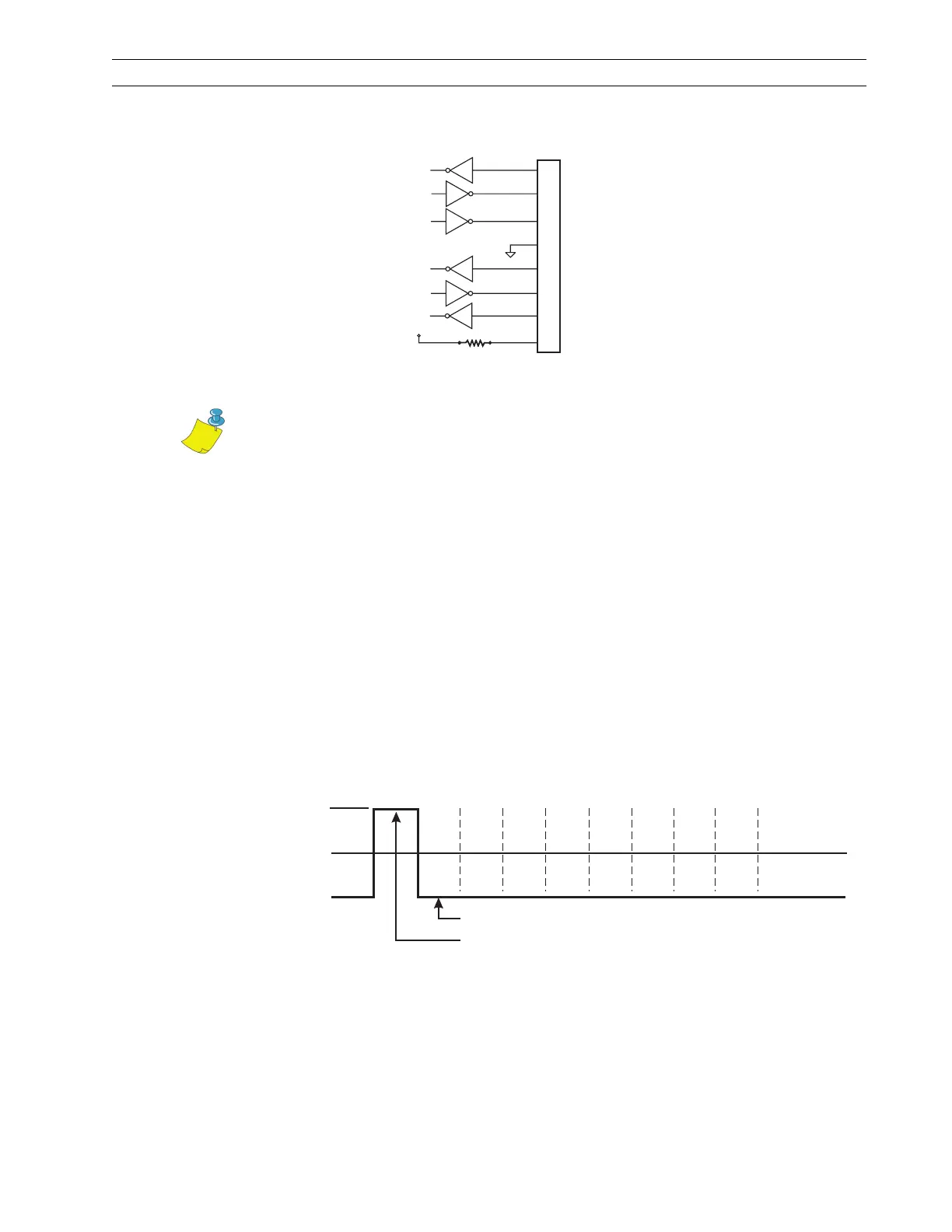
Figure 1-8. DB-9 RS-232 Connector
Serial Communication Signal Levels
Refer to Figure 1-9. RS-232 data signals are defined as either Mark or Space, while
control signals are On (l) (Active-Positive Voltage) or Off (O) (Inactive-Negative
Voltage). Although the permitted voltage levels can range from ±3 VDC to ±25 VDC, the
levels for the printer are as follows:
RS-232 Transmit and Receive Data
Mark or Off (O) = –7 to –10 VDC
Space or On (l) = +7 to +10 VDC
Figure 1-9. RS-232 Signaling
SG (
RXD (Receive Data Input)
TXD (Transmit Data Output)
DTR (Data Terminal Ready Output)
Signal Ground)
DSR (Data Set Ready Input)
RTS (Request To Send Output)
CTS (Clear to Send)
+5 VDC Source
2
3
4
5
6
7
8
9
1KW
R1
+5 VDC
RS-232 Connector (DTE)
Rear Panel DB-9
Notes • Pin 1 is unused and not terminated.
The cable used to connect the printer to a computer must be a null modem
(crossover) cable. To connect the printer to any other DTE devices, a null
modem cable must also be used.
+Space
0 VDC
– Mark
12
3
4
5
6
7
Logic 1
Logic 0
(idle)
Start
Bit
Parity
Bit
(idle)
Stop
Bit
Data Bits
{
{
{
{
 Loading...