13185L-002 Rev. A 1/24/06 110XiIIIPlus Maintenance Manual Page 5-17
Maintenance and Assembly Drawings Section 5
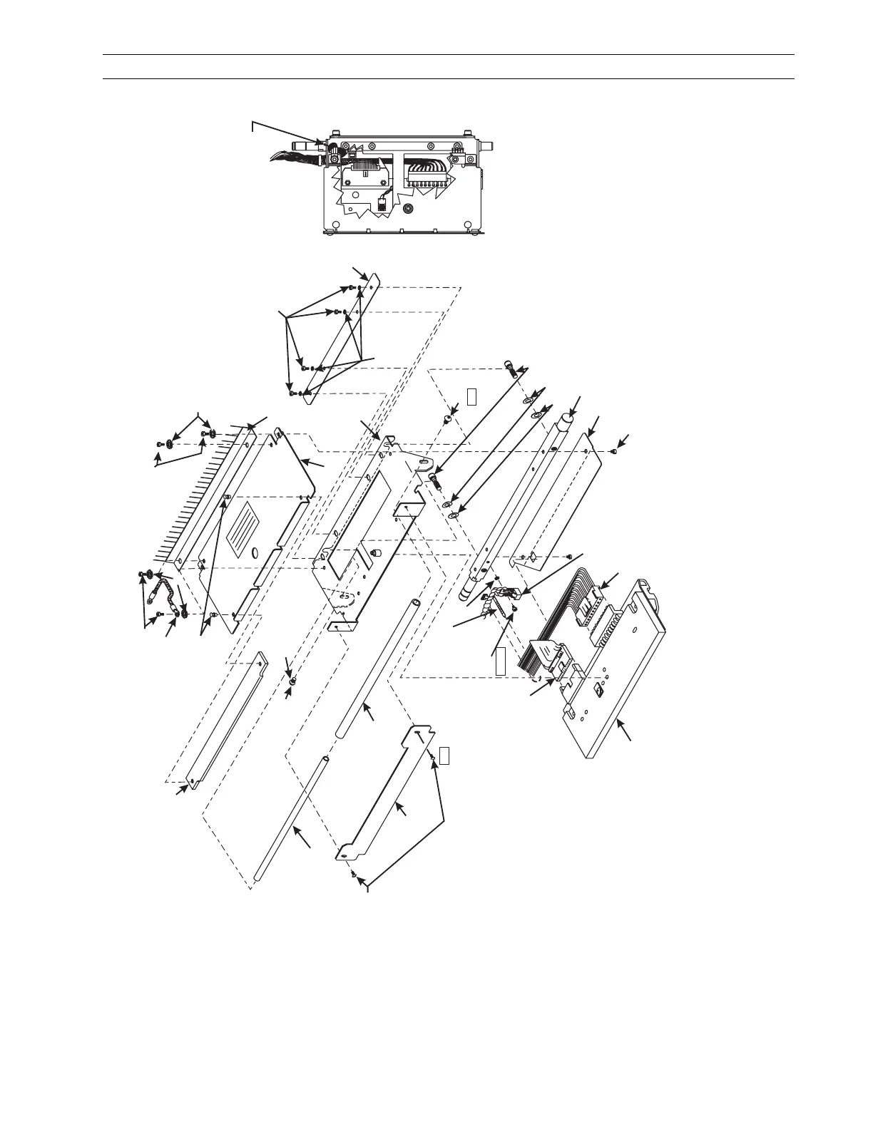
Figure 5-6. Printhead Support Assembly
2
3
13
2
15
2
26
25
24
18
16
20
7
4
2
Notes:
•
1. Position ribbon sensor (46665) tab so it is not
flush with top edge of pivot bar.
Gap 0.010 inch min./0.030 inch max. (0.26 mm/0.77 mm)
below top edge.
2. Screw tightening torques unless
otherwise specified to be 10–12 inch pounds
(1.1–1.3 N m).
Other values appear in boxes in inch pounds.
23
(See Note 1.)
21
19
8
9
11
12
14
17
Wrap ground strap
as shown.
6
(Adhesive
this side only)
3
5–6
1/2–3/4
10
6–8
27
1
5
22
28
16
 Loading...