13185L-002 Rev. A 1/24/06 110XiIIIPlus Maintenance Manual Page 5-31
Maintenance and Assembly Drawings Section 5
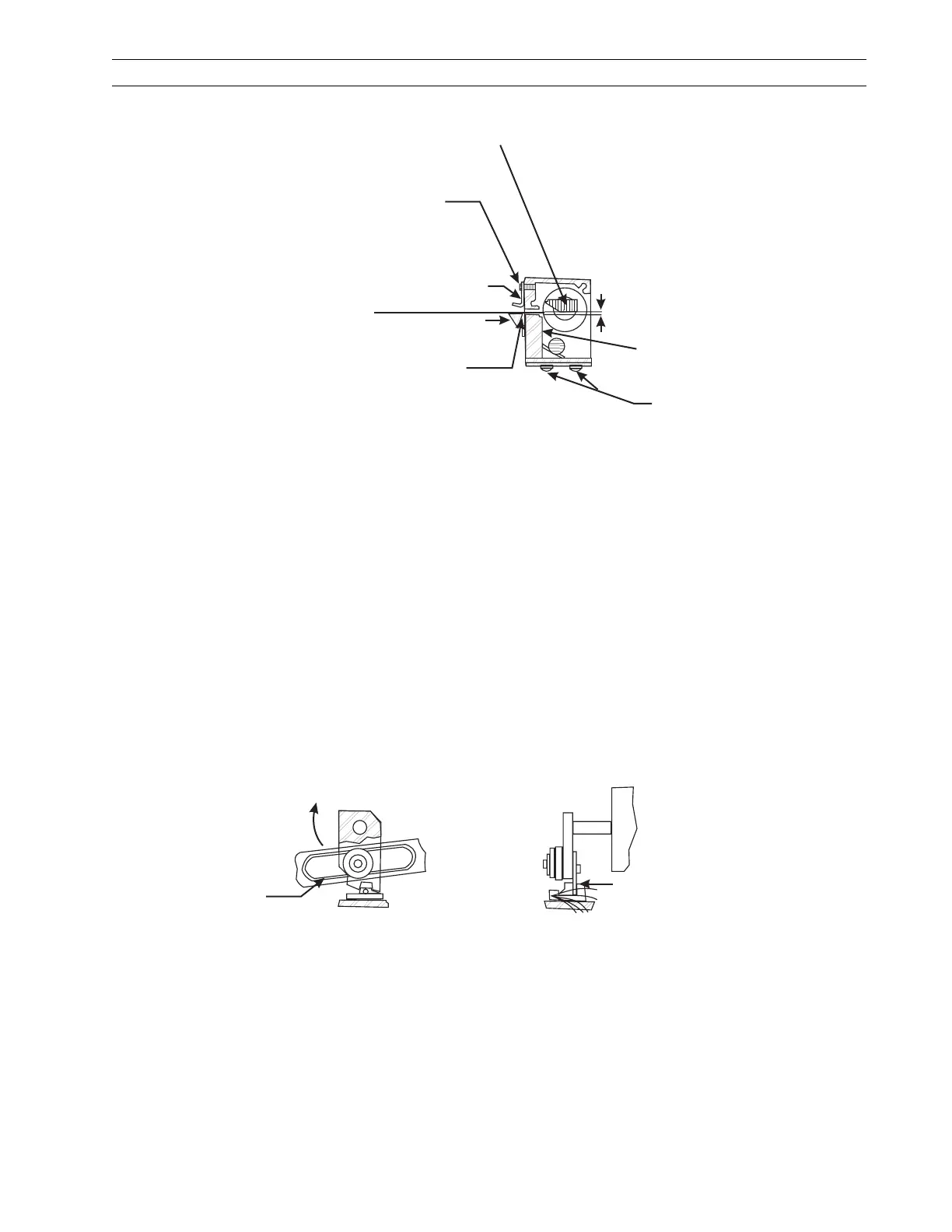
Figure 5-14. Cutter Option Assembly (View 2)
Relative position of rotary cutter
blade when the drive link assembly is
stopped by the optical sensor, when
power is on in cutter mode.
0.100 in. (2.5 mm)
10421 Screws (4) control
position of cutter module
and squareness to media.
Rear Cutter
Blade
Rotary Cutter Blade
Media Guide
Upper Cutter Bracket
Mounting Screw
Tear-off
Bar
Clearance of 0.030 in. (0.77 mm)
minimum between rear cutter blade
and tear-off bar.
Ensure the top of the tear-off
bar is positioned above
or level with the top of
the rear cutter blade.
Set screws to engage flats
on motor shaft when lower
arm is in vertical position.
Motor
Shaft
Cable holder
(30313) to be
placed securely
over cables.
Motor
Rotation
Direction
01660
Grease
all around
Black Flag to be
centered in optical
assembly
Front View
Side View
 Loading...