Rockwell Automation Publication 2198-UM002G-EN-P - February 2019 103
Connector Data and Feature Descriptions Chapter 4
DC Bus and Shunt Resistor Connector Pinouts
The 2198-Pxxx DC-bus power supply RC connector wires to an external
passive shunt when the internal shunt capacity is exceeded. The 2198-RPxxx
regenerative bus supply has no internal shunt and the RC connector wires to an
external active shunt.
Table 33 - DC Bus Power Connector
Table 34 - Shunt Connector
Digital Inputs Connector Pinouts
The DC-bus power supply has two configurable digital inputs and four
configurable functions to choose from in the Logix Designer application.
Table 35 - DC-bus Power Supply Digital Input Pinouts
Table 36 - DC-bus Power Supply Configurable Functions
DC Pin Description Signal Module
Bus bar DC bus connections
DC– • DC-bus power supply
• Regenerative bus supply
•Inverters
• Accessory modules
•iTRAK power supply
DC+
RC Pin Description Signal Module
1
Passive shunt connections
SH
DC-bus power supply
2DC+
1
Active shunt connections
DC–
Regenerative bus supply
2DC+
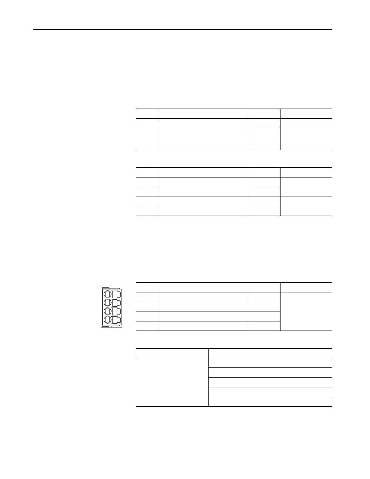
IOD Pin Description Signal Module
1 24V current sinking fast input #1 IN1
DC-bus power supply
2 I/O common for customer-supplied 24V supply COM
3 24V current sinking fast input #2 IN2
4 I/O cable shield termination SHLD
Default Configuration Description
Digital input1 = Enable
Digital input2 = Unassigned
Unassigned
Enable
Bus Capacitor OK
Shunt Thermal Switch OK
Bus Conditioner OK
Pin Orientation for 4-pin
Digital Inputs (IOD) Connector
Pin 1
Pin 4
 Loading...


