84 Rockwell Automation Publication 2198-UM002G-EN-P - February 2019
Chapter 3 Mount the Kinetix 5700 Drive System
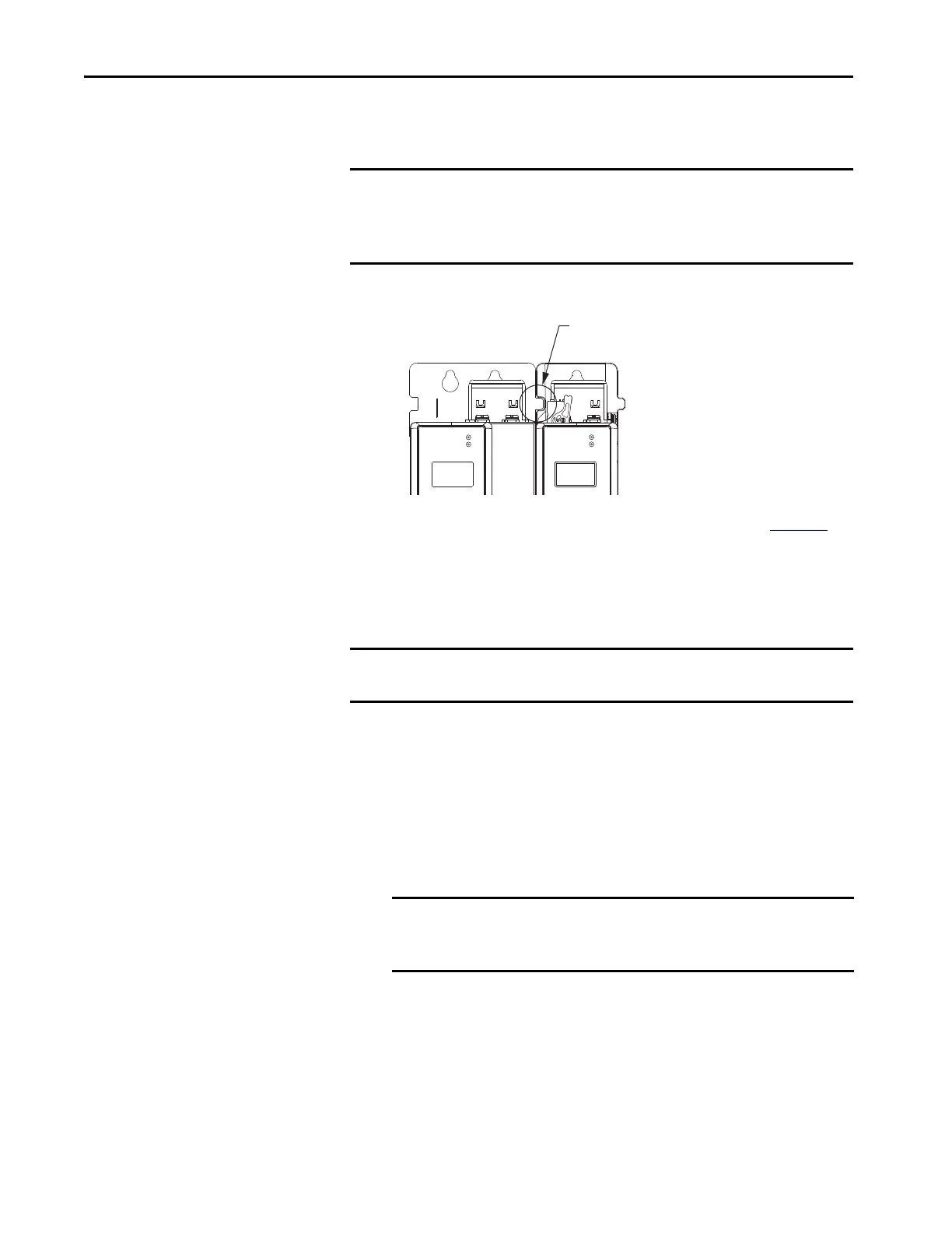
Zero-stack Tab and Cutout
Engaging the zero-stack tab and cutout from one drive module to another
makes efficient use of panel space, especially for high axis-count installations.
Figure 48 - Zero-stack Tab and Cutout Example
For Kinetix 5700 system sizing examples, refer to Appendix C on page 391.
Install Shared-bus
Connection Systems
The shared-bus connection system is used to extend the DC-bus power and
24V control power from one drive module to another.
DC-bus Connection System
The DC-bus connection system is required and comprised of these two
components:
• DC-bus links that are inserted between drive modules to extend the
DC-bus from one drive module to another.
• DC-bus end-caps that are inserted into the first and last drive modules
to cover the exposed DC-bus connector on both ends of the bus.
IMPORTANT Engaging the zero-stack tab and cutout from module-to-module is
required for any input power configuration. This is done to make sure that
the DC-bus connectors are spaced properly to accept the shared-bus
connection system.
Kinetix 5700 Drive Modules
(front view)
Zero-stack Tab
and Cutout Engaged
IMPORTANT The zero-stack tab and cutout must be engaged between adjacent drive
modules for the shared-bus connection system to fit properly.
IMPORTANT DC-bus links are included with inverter and accessory modules, so
when two or three 2198-P208 DC-bus power supplies are connected
in parallel, order extra 2198-BARCON-85DC200 DC-bus links.
 Loading...


