Rockwell Automation Publication 2198-UM002G-EN-P - February 2019 261
Configure and Start the Kinetix 5700 Drive System Chapter 6
Sine/Cosine with Hall Feedback
In this example, a motor feedback device is configured for Sine/Cosine with
UVW feedback.
1. In the Controller Organizer, right-click an axis and choose Properties.
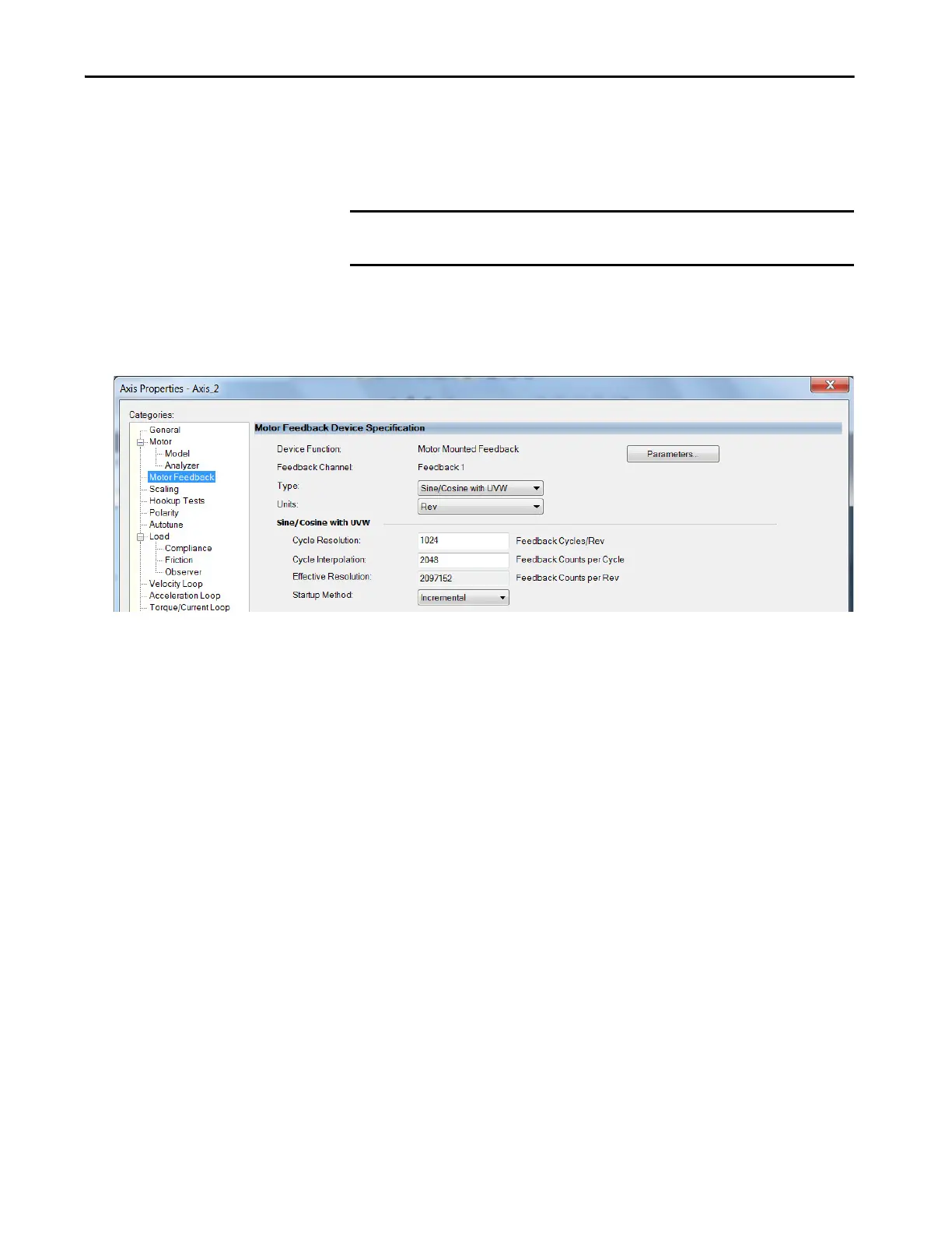
2. Select the Motor Feedback category.
The Motor Feedback Device Specification dialog box appears.
3. Configure the device function and type.
In this example, Motor Feedback is the device function and Sine/Cosine
with UVW is the feedback type.
4. Enter values for the Sine/Cosine with UVW specification fields.
The only valid values for Cycle Interpolation are powers of 2 from 4
through 65536.
5. From the Startup Method pull-down menu, choose Incremental.
6. From the Alignment pull-down menu, choose Not Aligned.
7. Click OK.
Download the Program
After completing the Logix Designer application and saving the file you must
download your program to the Logix 5000 processor.
IMPORTANT When Motor Mounted Feedback is the Device Function, Sine/Cosine with
UVW is the only valid feedback type for permanent magnet motors.
 Loading...


