Rockwell Automation Publication 2198-UM002G-EN-P - February 2019 105
Connector Data and Feature Descriptions Chapter 4
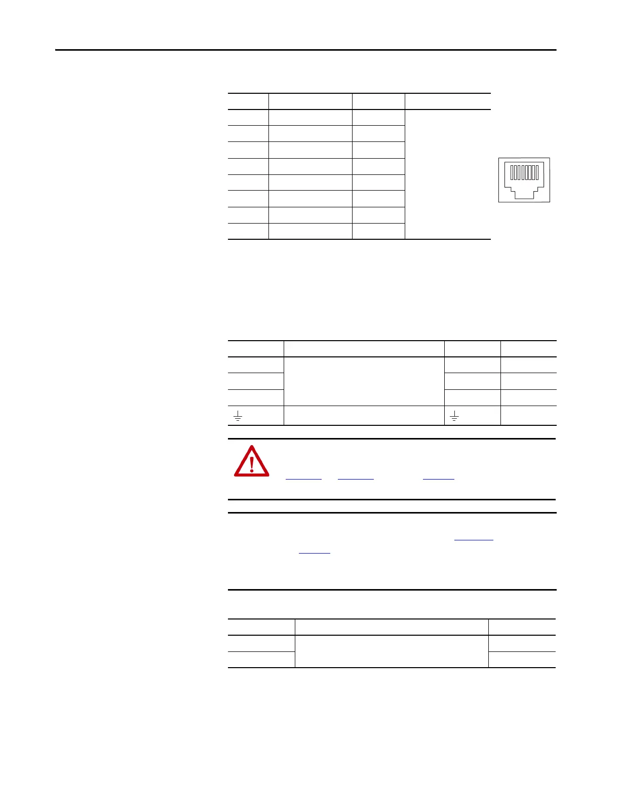
Ethernet Communication Connector Pinout
Motor Power, Brake, and Feedback Connector Pinouts
These connector pinouts apply to the single-axis and dual-axis inverter.
Table 40 - Motor Power Connector
Table 41 - Motor Brake Connector
Pin Description Signal Module
1 Transmit+ TD+
• DC-bus power supply
• Regenerative bus supply
•Inverters
•iTRAK power supply
2 Transmit– TD–
3 Receive+ RD+
4 Reserved –
5 Reserved –
6 Receive– RD–
7 Reserved –
8 Reserved –
MP Pin Description Signal Color
U
Three-phase motor power
UBrown
VVBlack
WWBlue
Chassis ground Green
ATTENTION: To avoid damage to the Kinetix 5700 system power supply and
inverter, make sure the motor power signals are wired correctly. Refer to
Figure 100
and Figure 101 beginning on page 153 for connector wiring
examples.
IMPORTANT Drive-to-motor power cables must not exceed 90 m (295 ft), depending on
feedback type and overall system design. See Appendix D
, beginning on
page 401
, for more information.
System performance was tested at this cable length. These limitations also
apply when meeting CE requirements.
BC Pin Description Signal
1
Motor brake connections
MBRK+
2MBRK–
1
8
 Loading...


