Rockwell Automation Publication 2198-UM002G-EN-P - February 2019 359
Interconnect Diagrams Appendix A
Passive Shunt Wiring
Examples
Wiring from the Bulletin 2198 shunt modules and resistor are made directly to
the shunt (RC) connector. You can configure either of the DC-bus power
supply digital inputs as Shunt Thermal Switch OK in the Logix Designer
application. Refer to page 205
to see how the DC-bus power supply Digital
Input category is configured.
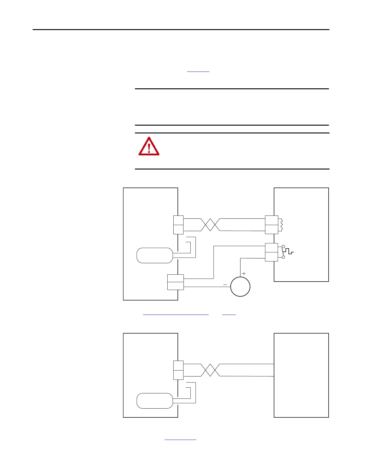
Figure 182 - DC-bus Power Supply with External Passive Shunt Module
(1) Configure either of two digital inputs as Shunt Thermal Switch OK. For DC-bus power supply configurable functions, see the
DC-bus Power Supply Configurable Functions
table on page 103.
Figure 183 - DC-bus Power Supply with External Passive Shunt Resistor
Refer to the Kinetix 5700 Passive Shunt Module Installation Instructions,
publication 2198-IN011
, for additional installation information.
IMPORTANT Passive shunts attach to only 2198-Pxxx DC-bus power supplies. Before
wiring the Bulletin 2198 external shunt to the RC connector, remove the
wires from the internal servo-drive shunt. Do not connect both internal and
external shunt resistors to the DC-bus power supply.
ATTENTION: To avoid damage to the Kinetix 5700 drive system, wire the
2198-R014, 2198-R031, or 2198-R127 shunt thermal switch to a digital input
on the DC-bus power supply and configure the Shunt Thermal Switch OK
function in the Logix Designer application.
DC+
SH
R1
R2
24V DC
(1)
INx
COM
TS
TS
2198-Pxxx
DC-bus Power Supply
Shunt (RC)
Connector
Internal Shunt
2198-R014, 2198-R031,
and 2198-R127 External
Passive Shunt Module
Resistor
Thermal Switch
Digital Input
(IOD) Connector
2198-Pxxx
DC-bus Power Supply
Shunt (RC)
Connector
Internal Shunt
2198-R004 External
Passive Shunt Resistor
 Loading...


