88 Rockwell Automation Publication 2198-UM002G-EN-P - February 2019
Chapter 3 Mount the Kinetix 5700 Drive System
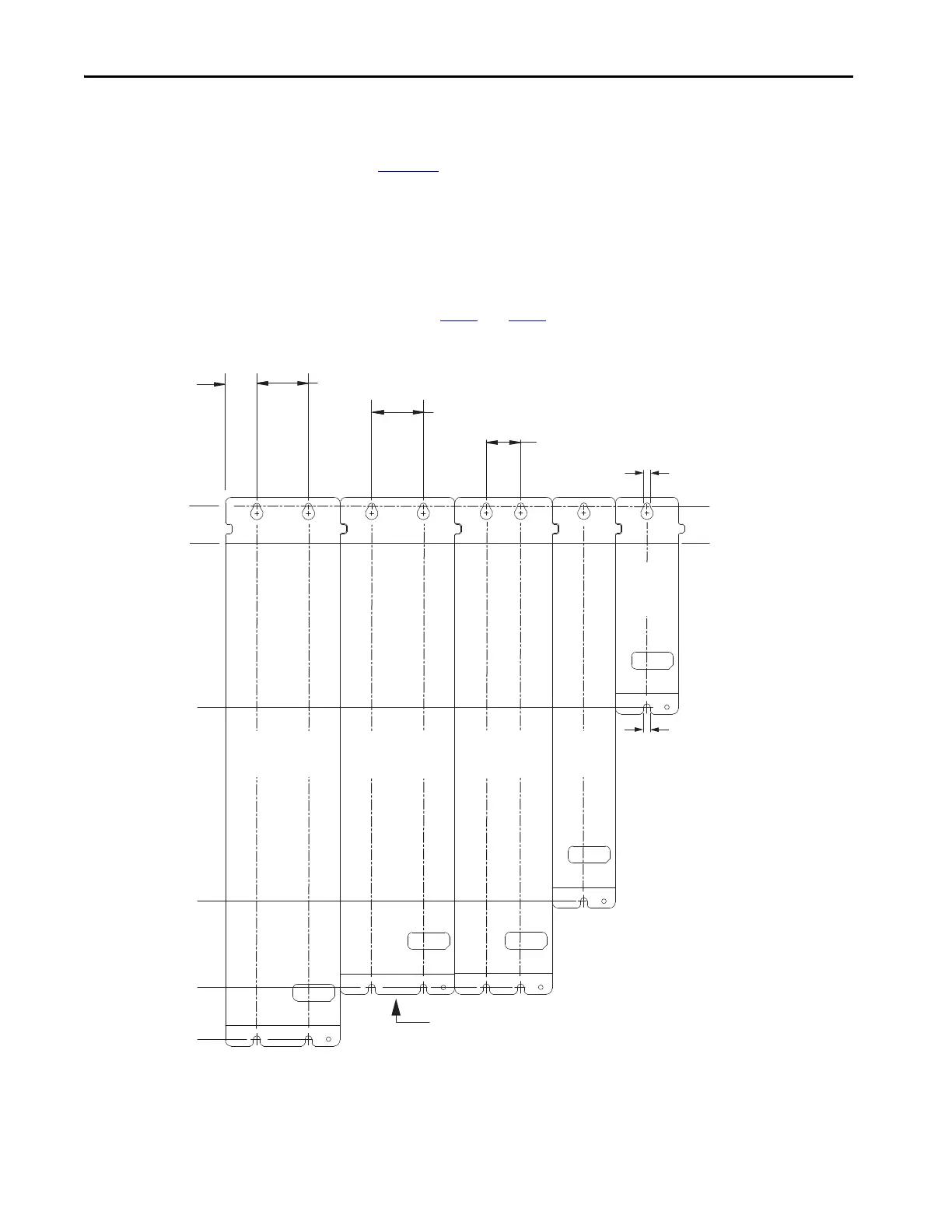
Drill-hole Pattern Calculations
Use Figure 52 to calculate the left-to-right hole pattern for Kinetix 5700 drive
system configurations that include the 2198-Pxxx DC-bus power supply.
1. The first hole location is zero.
2. The second hole location is module width minus 55 mm.
3. The next hole location is 55 mm.
4. Repeat step 2
and step 3 for the remaining holes.
Figure 52 - DC-bus Power Supply Mounting Hole Patterns
32.0 mm
Module Top, reference
27.5 mm
Module Top, reference
176 mm
Lower Mounting Hole
345 mm
Lower Mounting Hole
420 mm
Lower Mounting Hole
465 mm
Lower Mounting Hole
Ø 6.0 mm
Typic al
Ø 6.0 mm Typical
00.0 mm
Upper Mounting Holes
45.0 mm See Mounting Hole Pattern Calculations
30.0 mm See Mounting Hole Pattern Calculations
100 mm
Wide Module
85 mm
Wide Module
55 mm
Wide Module
55 mm
Wide Module
Applies to only 2198-S160-ERSx
Single-axis Inverter
Applies to 2198-P141, 2198-P208 Power Supplies
2198-S086-ERSx and 2198-S130-ERSx Inverters,
and 2198-D057-ERSx Inverters
Applies to 2198-P031 and 2198-P070 Power Supplies
2198-D006-ERSx, 2198-D012-ERSx,
2198-D020-ERSx, and 2198-D032-ERSx, Inverters
2198-CAPMOD-2240 Capacitor Module
2198-DCBUSCOND-RP312 DC-bus Conditioner Module
First Mounting Hole
(typical) Upper and Lower
Mounting Hole
(all drive modules)
Applies to only
2198-CAPMOD-DCBUS-IN
Extension Module
45.0 mm See Mounting Hole Pattern Calculations
100 mm
Wide Module
Applies to only 2198T-W25K-ER
iTRAK Power Supply
 Loading...


