56 Rockwell Automation Publication 2198-UM002G-EN-P - February 2019
Chapter 2 Plan the Kinetix 5700 Drive System Installation
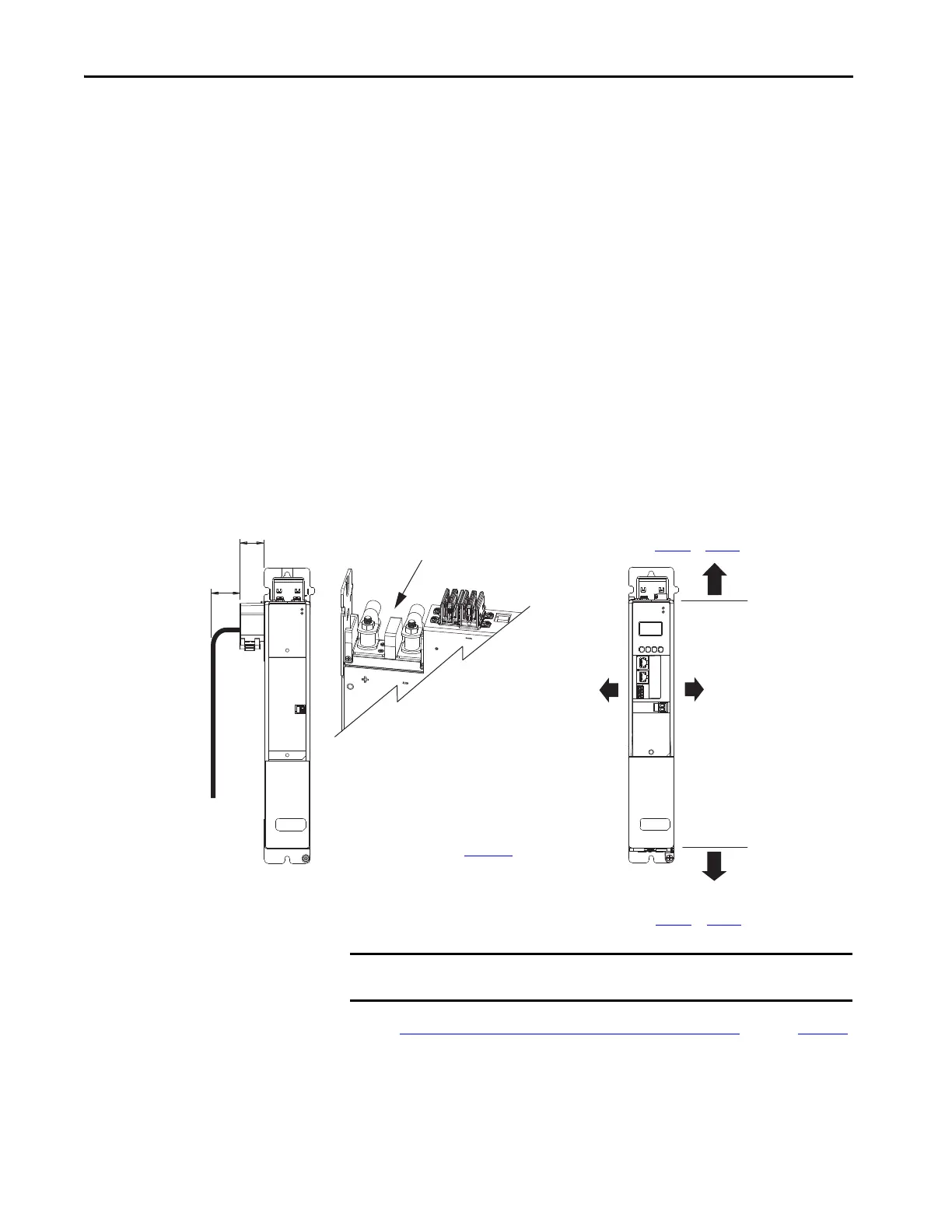
Minimum Clearance Requirements
This section provides information to assist you in sizing your cabinet and
positioning your Kinetix 5700 drive system:
• Additional clearance is required for cables and wires or the shared-bus
connection system connected to the top of the drive modules.
– Accessory modules require extra clearance above for wiring DC-bus
stud connections and installing the cover.
• Additional clearance is required if other devices are installed above and/
or below the drive module and have clearance requirements of their
own.
– Accessory modules require extra clearance to route DC-bus wiring
into or away from the drive system.
• Additional clearance left and right of the drive module is required when
mounted adjacent to noise sensitive equipment or clean wire ways.
• The recommended minimum cabinet depth is 300 mm (11.81 in.).
Figure 20 - Minimum Clearance Requirements
See the Kinetix 5700 Drive Module Clearance Specifications table on page 57
for clearance specifications.
MOD
NET
2
1
1
4
I/O
MODULE
STATUS
MOD
DC BUS
29.5
(1.16)
Clearance right of the
module is not required.
Clearance left of the
module is not required.
Kinetix 5700 Drive Module
(DC-bus power supply is shown)
Clearance below module
for airflow and installation
(see Table 1 9 on page 57 for values).
Clearance above module
for airflow and installation
(see Tab le 1 9
on page 57 for values).
Refer to the Kinetix Servo Drives Technical
Data, publication KNX-TD003
, for
Kinetix 5700 drive module dimensions.
Kinetix 5700 Accessory Module
(2198-CAPMOD-2240 module is shown)
Clearance above for wiring to DC-bus
studs and lug cover installation.
Clearance where cover and
DC-bus cabling attaches.
IMPORTANT
Mount the drive module in an upright position as shown. Do not mount the module on its
side.
 Loading...


