Universal Feedback
(UFB) Connector
Motor Power
(MP) Connector
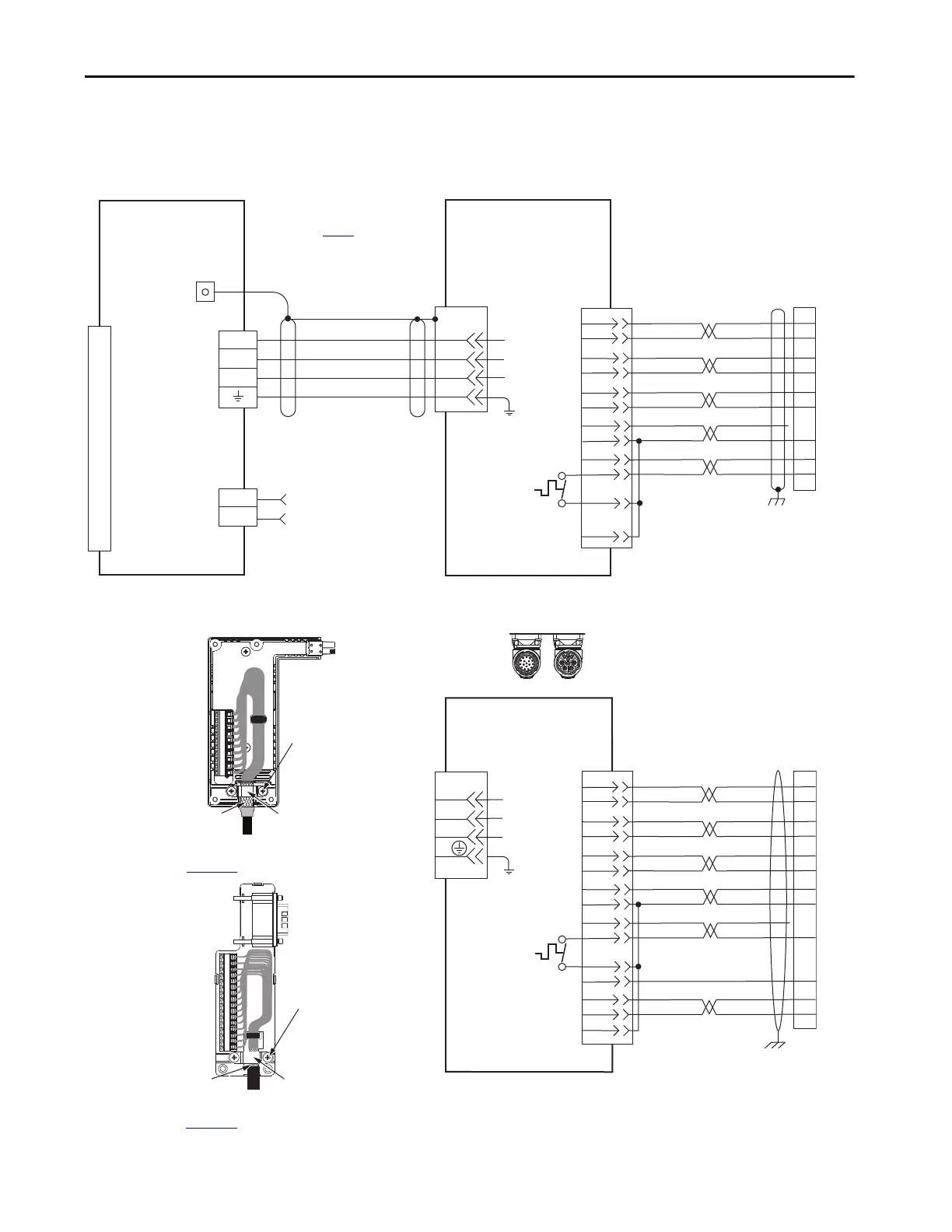
LDAT-Sxxxxxx-xDx
Linear Thrusters with
High Resolution Feedback
Motor Feedback
(MF) Connector
Three-phase
Motor Power
Motor
Feedback
Thermostat
Grounding Techniques for
Feedback Cable Shield
Cable Clamp
Exposed shield secured
under clamp.
Clamp Screws (2)
Refer to table on page 341 for note information.
Cable Shield
Clamp
Note 7
Power Connector
Feedback Connector
SpeedTec DIN
Motor Connectors
2090-CFBM7DF-CEAAxx (standard) or
2090-CFBM7DF-CEAFxx (continuous-flex)
(flying-lead) Feedback Cable
Note 19
2090-CPWM7DF-xxAAxx
(standard) or
2090-CPWM7DF-xxAFxx
(continuous-flex)
Motor Power Cable
Notes 19, 21
Refer to feedback kit
illustrations (lower left)
for proper grounding technique.
2198-H2DCK
Hiperface-to-DSL
Feedback Converter Kit
2198-Dxxx -ERSx
Kinetix 5700 Servo Drives
Refer to Hiperface to DSL Feedback Converter Kit Installation Instructions,
publication 2198-IN006
, for converter kit specifications.
2198-K57CK-D15M
Feedback
Connector Kit
Refer to Universal Feedback Connector Kit Installation Instructions,
publication 2198-IN010
, for connector kit specifications.
Cable Clamp
Exposed shield secured
under clamp.
Clamp Screws (2)
2198-K57CK-D15M
Universal Feedback
Connector Kit
Refer to Universal feedback
connector kit illustration (left)
for proper grounding technique.
2090-XXNFMF-Sxx (standard) or
2090-CFBM7DF-CDAFxx (continuous-flex)
(flying-lead) Feedback Cable
Notes 19
LDAT-Sxxxxxx-xBx
Linear Thrusters with
Incremental Feedback
2198-H2DCK Feedback
Converter Kit or
2198-K57CK-D15M Feedback
Connector Kit
Three-phase
Motor Power
Motor
Feedback
Thermostat
Note 8
 Loading...


