124 Rockwell Automation Publication 2198-UM002G-EN-P - February 2019
Chapter 4 Connector Data and Feature Descriptions
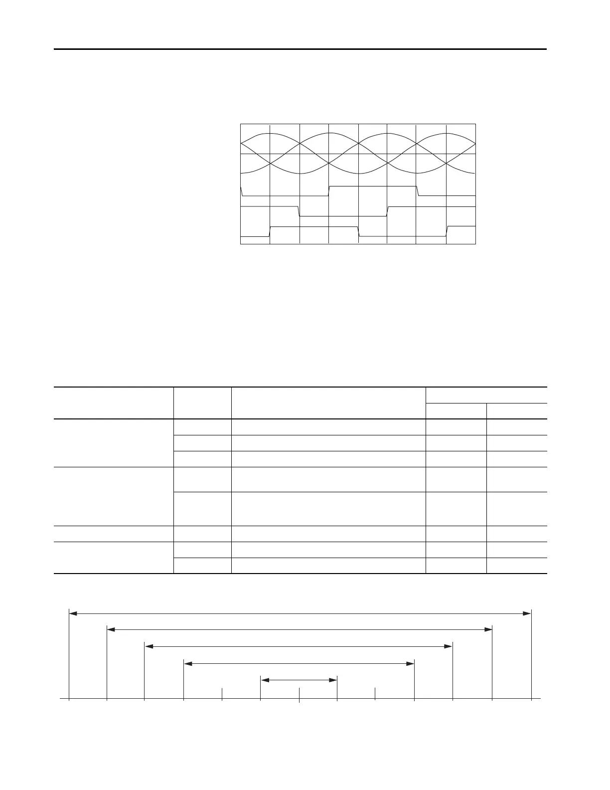
The drive UFB feedback connector uses Hall signals to initialize the
commutation angle for permanent magnet motor commutation.
Figure 78 - Hall Encoder Phasing
Absolute Position Feature
The absolute position feature tracks the position of the motor, within the
multi-turn retention limits, while the drive is powered off. The absolute
position feature is available with only multi-turn encoders.
Table 60 - Absolute Position Retention Limits
Figure 79 - Absolute Position Limits (measured in turns)
V
UN
V
WN
V
VN
S1
S2
S3
300
0
60 120 180 240 300 60
0
Encoder Type
Cat. No.
Designator
Motor/Actuator Cat. No.
Retention Limits
Turns (rotary) mm (in.) linear
Stegmann Hiperface (DSL)
-P VPL-Bxxxxx-P, VPF-Bxxxxx-P, VPS-Bxxxxx-P, VPAR-Bxxxxx-P 4096 (±2048) –
-W VPL-Bxxxxx-W, VPF-Bxxxxx-W, VPAR-Bxxxxx-W 4096 (±2048) –
-Q VPL-Bxxxxx-Q, VPF-Bxxxxx-Q, VPC-Bxxxxx-Q, VPAR-Bxxxxx-Q 512 (±256) –
Stegmann Hiperface
-M
MPL-Bxxxxx-M, MPM-Bxxxxx-M, MPF-Bxxxxx-M, MPS-Bxxxxx-M,
MPAR-B3xxxx-M, MPAI-BxxxxxM
2048 (±1024) –
-V
MPL-Bxxxxx-V,
MPAS-Bxxxx1-V05, MPAS-Bxxxx2-V20,
MPAR-B1xxxx-V, MPAR-B2xxxx-V, MPAI-BxxxxxV
4096 (±2048) –
Stegmann Hiperface (magnetic scale) -xDx LDAT-Sxxxxxx-xDx N/A 960 (37.8)
Heidenhain EnDat
-7 RDB-Bxxxxxx-7 1024 (±512) –
-Y VPC-Bxxxxx-Y 128 (±64) –
+2048-2048 +1024-1024
+64
-64
+256-256
+512
-512
0
-128
+128
Position at Power Down
4096 Turns
2048 Turns
512 Turns
128 Turns
1024 Turns
 Loading...


