400 Rockwell Automation Publication 2198-UM002G-EN-P - February 2019
Appendix C Size Multi-axis Shared-bus Configurations
System Sizing Application
Example
This example shows how to size the DC-bus power supply for your multi-axis
system by using the motor output power (kW). Sizing is based on the largest
motor kW value in your drive system.
The Kinetix 5700 drive modules are zero-stacked and use the shared-bus
connection system to extend power from the 2198-Pxxx DC-bus power supply
or 2198-RPxxx regenerative bus supply to multiple drive modules. For best
results, use the Motion Analyzer system sizing and selection tool, available at
https://motionanalyzer.rockwellautomation.com.
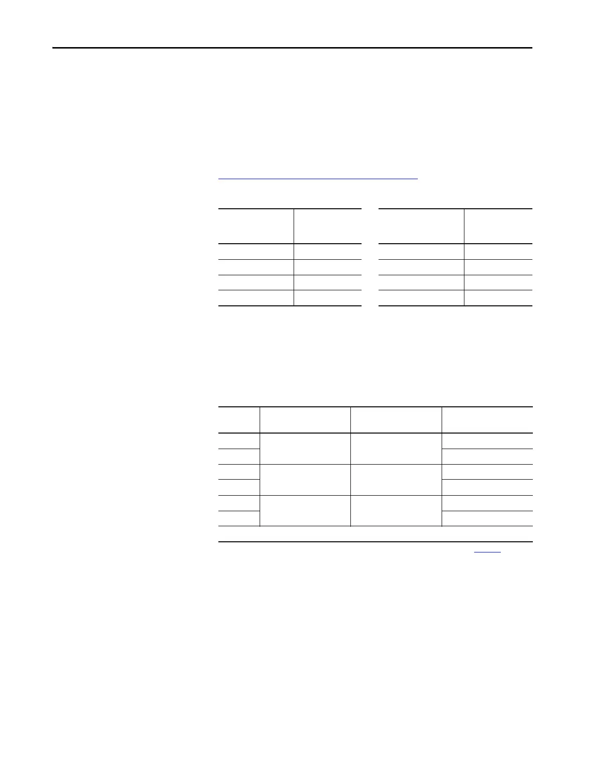
Table 178 - Kinetix 5700 System Power Supply Continuous Output Power
In this typical system, all axes are running in an asynchronous rapid
acceleration/deceleration motion profile. Use this formula to calculate the
minimum continuous output-power (kW) for your Kinetix 5700 drive system:
2198-Pxxx = Largest motor-rated kW x (axis-count x 0.6) + (axis-count x 0.2)
Table 179 - Motor/Drive System Example
Continuous Output Power, min (kW) = 7.2 x (8 x 0.6) + (8 x 0.2)
kW = 7.2 x 4.8 + 1.6
kW = 36.16
In this example, the MPM-B2153F motor has the largest motor-rated output.
As a result, the minimum continuous output-power = 36.16 kW, and the
2198-P208 DC-bus power supply or 2198-RP200 regenerative bus supply is
required for the 8-axis system example.
DC-Bus Power Supply
Cat. No.
Continuous Output
Power
kW
Regenerative Bus Supply
Cat. No.
Continuous Output
Power
kW
2198-P031 7 2198-RP088 24
2198-P070 17 2198-RP200 67
2198-P141 31 2198-RP263 119
2198-P208 46 2198-RP312 140
Motor
Quantity
Motor Cat. No.
Motor Rated Output
(1)
kW
(1) For more motor specifications, see the Kinetix Rotary Motion Specifications Technical Data, publication KNX-TD001.
Drive Cat. No.
1
MPM-B2153F 7.2
2198-S086-ERSx
1 2198-S086-ERSx
1
MPL-B660F 6.1
2198-S086-ERSx
1 2198-S086-ERSx
2
VPL-B0753 0.82
2198-D020-ERSx
2 2198-D020-ERSx
8 = axis count
 Loading...


