182 Rockwell Automation Publication 2198-UM002G-EN-P - February 2019
Chapter 5 Connect the Kinetix 5700 Drive System
External Passive-shunt
Connections
Passive shunts attach to only 2198-Pxxx DC-bus power supplies. See Passive
Shunt Considerations on page 51 for shunts compatible with your DC-bus
power supply.
Follow these guidelines when wiring your 2198-Rxxx passive shunt:
•Refer to External Passive Shunt Modules
on page 74 for noise zone
considerations.
•Refer to Passive Shunt Wiring Examples
on page 359.
• Refer to the installation instructions provided with your Bulletin 2198
shunt module, publication 2198-IN011
.
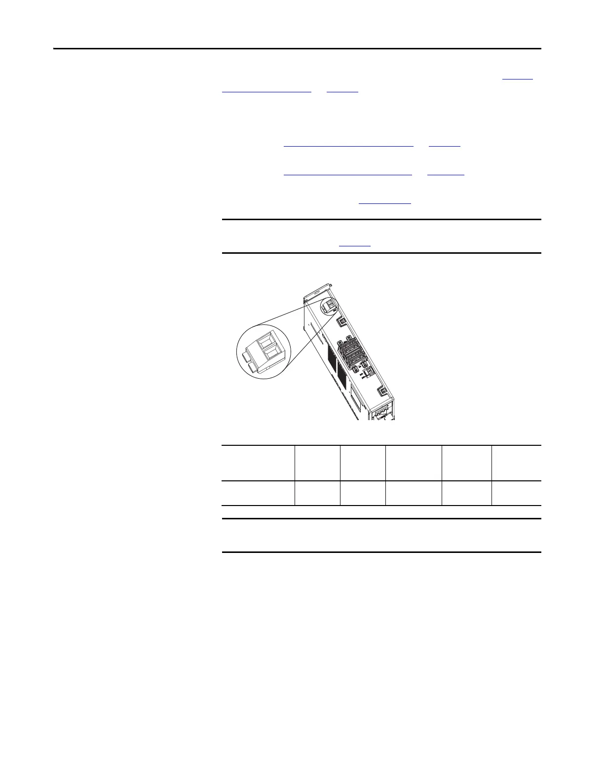
Figure 123 - RC Connector Wiring
Table 99 - Shunt Resistor (RC) Connector Specifications
IMPORTANT To improve system performance, run wires and cables in the wireways as
established in Chapter
2.
2198-Pxxx
DC-bus Power Supply
Top View
Shunt Resistor (RC) Connector Plug
DC-bus Power Supply
Cat. No.
Pin Signal
Recommended
Wire Size
mm
2
(AWG)
Strip Length
mm (in.)
Torque Value
N•m (lb•in)
2198-Pxxx
RC-1
RC-2
SH
DC+
1.5…6
(16…10)
12.0 (0.47)
0.5…0.6
(4.4…5.3)
IMPORTANT You must disconnect the internal shunt wires at the RC connector before
connecting the Bulletin 2198 passive shunt resistor wires.
 Loading...


