Rockwell Automation Publication 2198-UM002G-EN-P - February 2019 211
Configure and Start the Kinetix 5700 Drive System Chapter 6
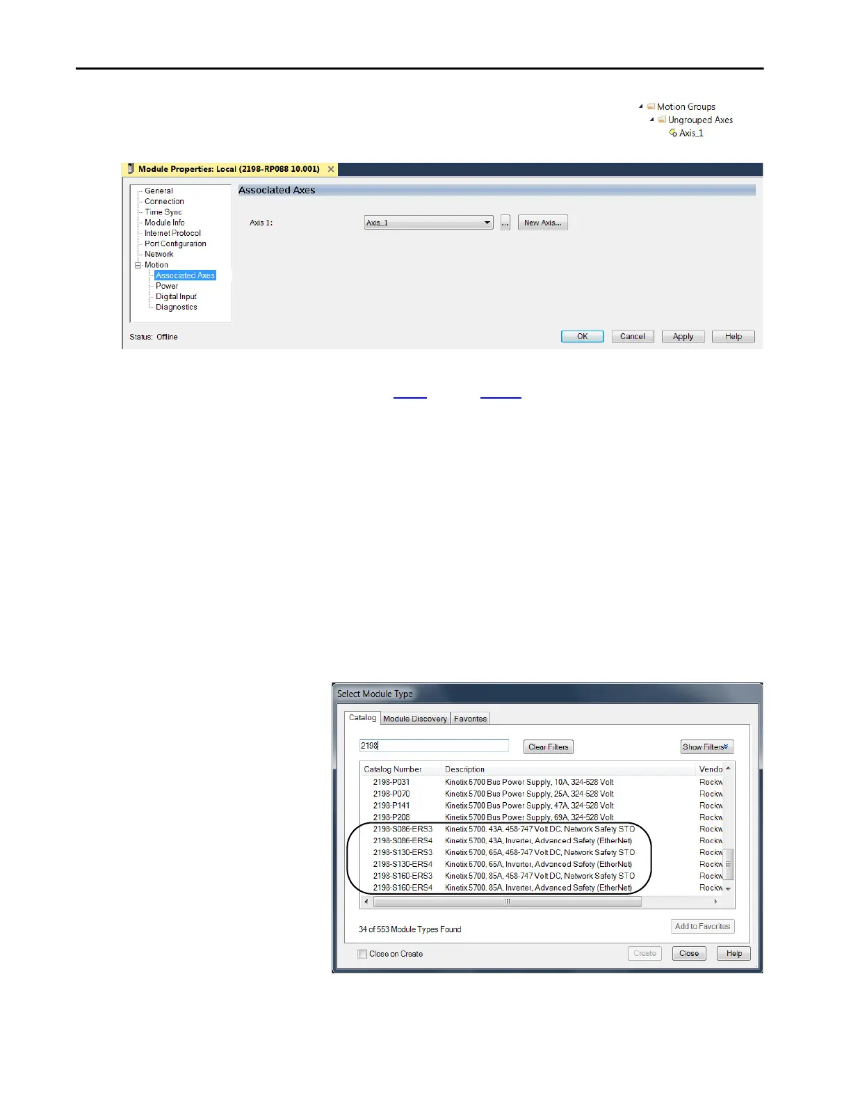
The axis (Axis_1 in this example) appears in the
Controller Organizer under Motion Groups>
Ungrouped Axes and is assigned as Axis 1.
17. Click Apply.
18. Repeat step 1
through step 17 if you have more than one 2198-RPxxx
regenerative bus supply.
Configure the Inverter Drives
This procedure applies to single-axis and dual-axis inverters with hardwired or
integrated safety connections. In this example, a 2198-D006-ERS4 dual-axis
inverter is configured.
Follow these steps to configure Kinetix 5700 inverter drives.
1. Above the DC-bus power supply (converter) you just created, right-click
Ethernet and choose New Module.
The Select Module Type dialog box appears.
This example shows the
2198-Sxxx-ERSx single-axis
inverters you can choose from.
 Loading...


