110 Rockwell Automation Publication 2198-UM002G-EN-P - February 2019
Chapter 4 Connector Data and Feature Descriptions
Contactor Enable Relay
The contactor-enable circuitry includes a relay-driven contact within the
2198-Pxxx DC-bus power supply and 2198-RPxxx regenerative bus supply.
The relay protects the Kinetix 5700 drive system in the event of overloads or
other fault conditions.
An AC three-phase mains contactor must be wired in series between the
branch circuit protection and the power supply. In addition, the AC three-
phase contactor control string must be wired in series with the contactor-
enable relay at the contactor-enable (CED) connector. Refer to Power Wiring
Examples on page 343 for wiring examples.
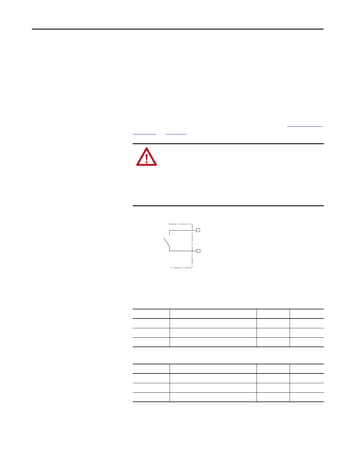
Figure 66 - Contactor-enable Relay Circuit
Surge suppression (diode, varistor module, RC module, or DC electronic
interface) is required across the auxiliary and main contactor coils.
Table 47 - Regenerative Bus Supply (CED) Relay Output Specifications
Table 48 - DC-bus Power Supply (CED) Relay Output Specifications
ATTENTION: Wiring the contactor-enable relay is required. To avoid personal
injury or damage to the drive, wire the contactor-enable relay into your
control string so that:
• three-phase power is removed and the power supply is protected under
various fault conditions.
• three-phase power is never applied to the Kinetix 5700 drive system before
control power is applied.
CONT EN-
CONT EN+
Normally
Open
Relay
Power Supply
Attribute Value Nominal Maximum
On-state current Current flow when the relay is closed. – 1 A
On-state resistance Contact resistance when the relay is closed. 0.1 Ω –
Off-state voltage Voltage across the contacts when the relay is open. 24V DC 28V DC
Attribute Value Nominal Maximum
On-state current Current flow when the relay is closed. – 1 A
On-state resistance Contact resistance when the relay is closed. 1.0 Ω –
Off-state voltage Voltage across the contacts when the relay is open. 24V DC 28V DC
 Loading...


