52 Rockwell Automation Publication 2198-UM002G-EN-P - February 2019
Chapter 2 Plan the Kinetix 5700 Drive System Installation
Active Shunt Considerations
External active shunts are required in the following use cases:
• The 2198-RPxxx regenerative bus supply provides DC-bus power while
DC-bus regulation is not enabled.
• One permanent magnet motor runs above its bus overvoltage speed. See
Field Weakening Mode
on page 446 for a description of this feature.
• One permanent magnet motor drives a vertical load that could make the
motor accelerate above the bus overvoltage speed during a fault
condition.
• Any condition where total shared DC-bus regenerative power is greater
than the 2198-RPxxx regenerative bus supply capacity. For example,
consider a peak-power stopping condition.
• The 2198-RPxxx regenerative bus supply is operating with DC-bus
regulation enabled and the regenerative bus supply loses three-phase AC
input power, 24V DC input power, or has a fault condition.
Active shunts are available from the Rockwell Automation Encompass™ partner
Powerohm Resistors, Inc. See http://www.powerohm.com
for more
information on Powerohm active shunts.
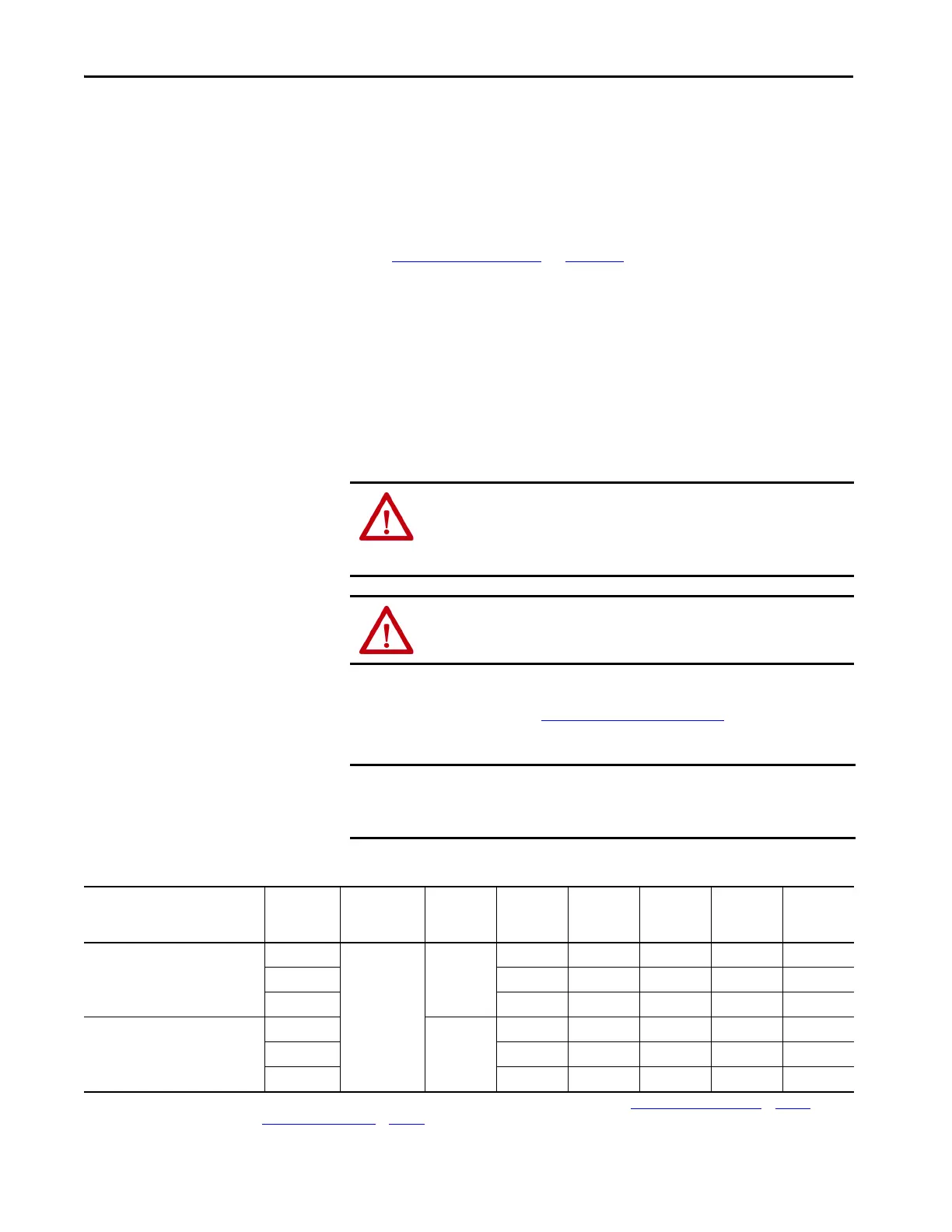
Table 16 - Compatible Active Shunt Specifications (internal brake resistor)
ATTENTION: To avoid damage to the Kinetix 5700 drive system, wire the
active shunt thermal switch to a digital input on the power supply and
configure the Shunt Thermal Switch OK function in the Logix Designer
application.
ATTENTION: DC-bus failure can cause damage to all drive modules in the
bus group, not just the inverter connected to the motor.
IMPORTANT Powerohm Bulletin PKBxxx active shunt modules use built-in internal brake
resistors. Bulletin PWBxxx active shunt modules require appropriately sized
external brake resistors.
Kinetix 5700 Power Supply
Powerohm
Resistors
Cat. No.
(1)
Input Voltage,
nom
Turn -on
Bus Voltage
Continuous
Power
kW
Resistance
(internal)
Ω
Resistance
(minimum)
Ω
Continuous
Current
Amps
Peak
Current
Amps
2198-Pxxx DC-bus power supply or
2198-RPxxx regenerative bus supply
when DC-bus regulation is not enabled.
PKB005
480V AC
750V DC
1.50 108 – 2.00 6.9
PKB010 2.06 52.7 – 2.75 14.2
PKB050 7.00 10.5 – 9.30 71.4
2198-RPxxx regenerative bus supply
when DC-bus regulation is enabled.
PKB005-800
800V DC
1.50 108 – 1.88 7.4
PKB010-800 2.06 52.7 – 2.58 15.2
PKB050-800 7.00 10.5 – 8.72 76.2
(1) How the Powerohm PKBxxx shunts connect to the 2198-Pxxx DC-bus power supply and 2198-RPxxx regenerative bus supply is explained in External Active-shunt Connections on page 183 and
illustrated with interconnect diagrams in Active Shunt Wiring Examples
on page 360.
 Loading...


