358 Rockwell Automation Publication 2198-UM002G-EN-P - February 2019
Appendix A Interconnect Diagrams
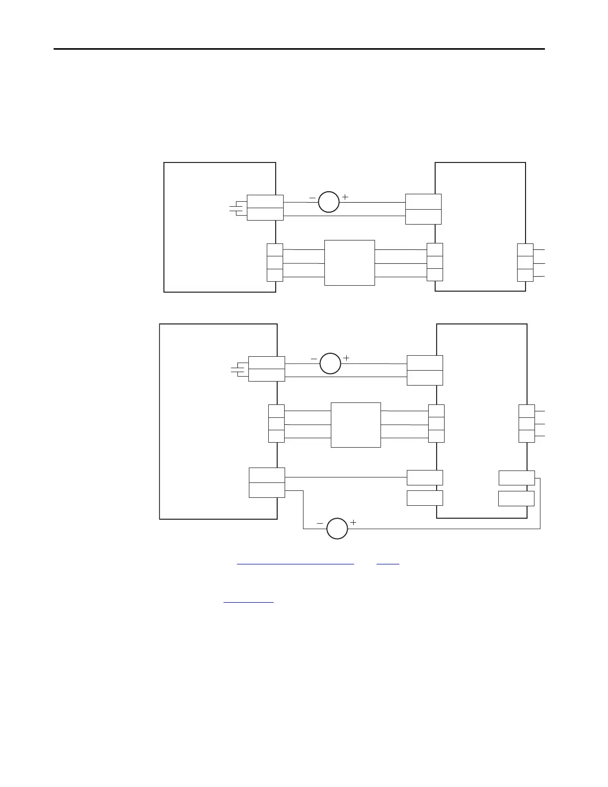
Contactor Wiring Examples
We recommend that you wire an Allen-Bradley® (Bulletin 100) auxiliary
contactor to the 2198-RPxxx regenerative-bus supply digital input (IOD
connector) and configure AC Line Contactor OK to monitor three-phase
input power. Use the Normally Open (N.O.) auxiliary contact, if more than
one auxiliary contact is available.
Figure 180 - Contactor Wiring for DC-bus Power Supply
Figure 181 - Contactor Wiring for Regenerative Bus Supply
(1) Configure digital input #2 as AC Line Contactor OK (default setting). For regenerative bus supply configurable functions, see the
Regenerative Bus Supply Configurable Functions
table on page 104.
Refer to IEC Contactor Specifications Technical Data, publication
100-TD013
, for additional contactor related information.
24V DC
CONT EN+
CONT EN–
CONT EN+
CONT EN–
L1
L2
L3
L1
L2
L3
L1
L2
L3
2198-Pxxx
DC-bus Power Supply
Allen-Bradley
Bulletin 100 Contactor
AC Input Power
(IPD) Connector
Contactor Enable
(CED) Connector
2198-DBRxx-F
AC Line Filter
24V DC
CONT EN+
CONT EN–
CONT EN+
CONT EN–
L1
L2
L3
L1
L2
L3
AC Line
Filter
L1
L2
L3
24V DC
INx
COM
AUX N.O.
AUX N.C.
AUX N.O.
AUX N.C.
2198-RPxxx
Regenerative Bus Supply
Digital Input
(IOD) Connector
Allen-Bradley
Bulletin 100 Contactor
AC Input Power
(IPD) Connector
Contactor Enable
(CED) Connector
2198-DBRxx-F
AC Line Filter
 Loading...


