Rockwell Automation Publication 2198-UM002G-EN-P - February 2019 357
Interconnect Diagrams Appendix A
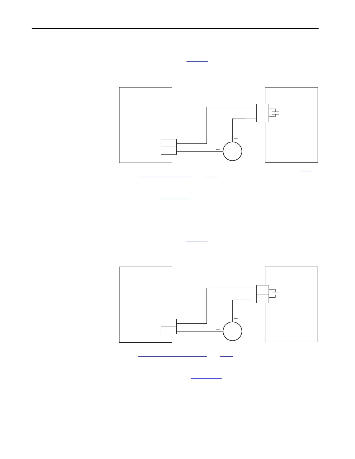
Capacitor Module Status
Wiring Example
You can configure either of the DC-bus power supply digital inputs as Bus
Capacitor OK in the Logix Designer application to monitor the Module
Status output. Refer to page 205
to see how the DC-bus power supply Digital
Inputs category is configured.
Figure 178 - DC-bus Power Supply with Capacitor Module
(1) Configure either of two digital inputs as Bus Capacitor OK. For DC-bus power supply configurable functions, see the DC-bus
Power Supply Configurable Functions table on page 103.
Refer to the Kinetix 5700 Capacitor Modules Installation Instructions,
publication 2198-IN008
, for additional installation information.
DC-bus Conditioner Module
Status Wiring Example
You can configure any of the regenerative bus supply digital inputs as Bus
Conditioner OK in the Logix Designer application to monitor the Module
Status output. Refer to page 209
to see how the regenerative bus supply Digital
Inputs category is configured.
Figure 179 - Regenerative Bus Supply with DC-bus Conditioner Module
(1) Configure any one of four digital inputs as Bus Conditioner OK. For regenerative bus supply configurable functions, see the
Regenerative Bus Supply Configurable Functions
table on page 104.
Refer to the Kinetix 5700 DC-bus Conditioner Module Installation
Instructions, publication 2198-IN016
, for additional installation information.
2198-Pxxx
DC-bus Power Supply
2198-CAPMOD-2240
Capacitor Module
Module Status
(MS) Connector
Digital Input
(IOD) Connector
2198-RPxxx
Regenerative Bus Supply
2198-DCBUSCOND-RP312
DC-bus Conditioner Module
Module Status
(MS) Connector
Digital Input
(IOD) Connector
 Loading...


