20 Rockwell Automation Publication 2198-UM002G-EN-P - February 2019
Chapter 1 Start
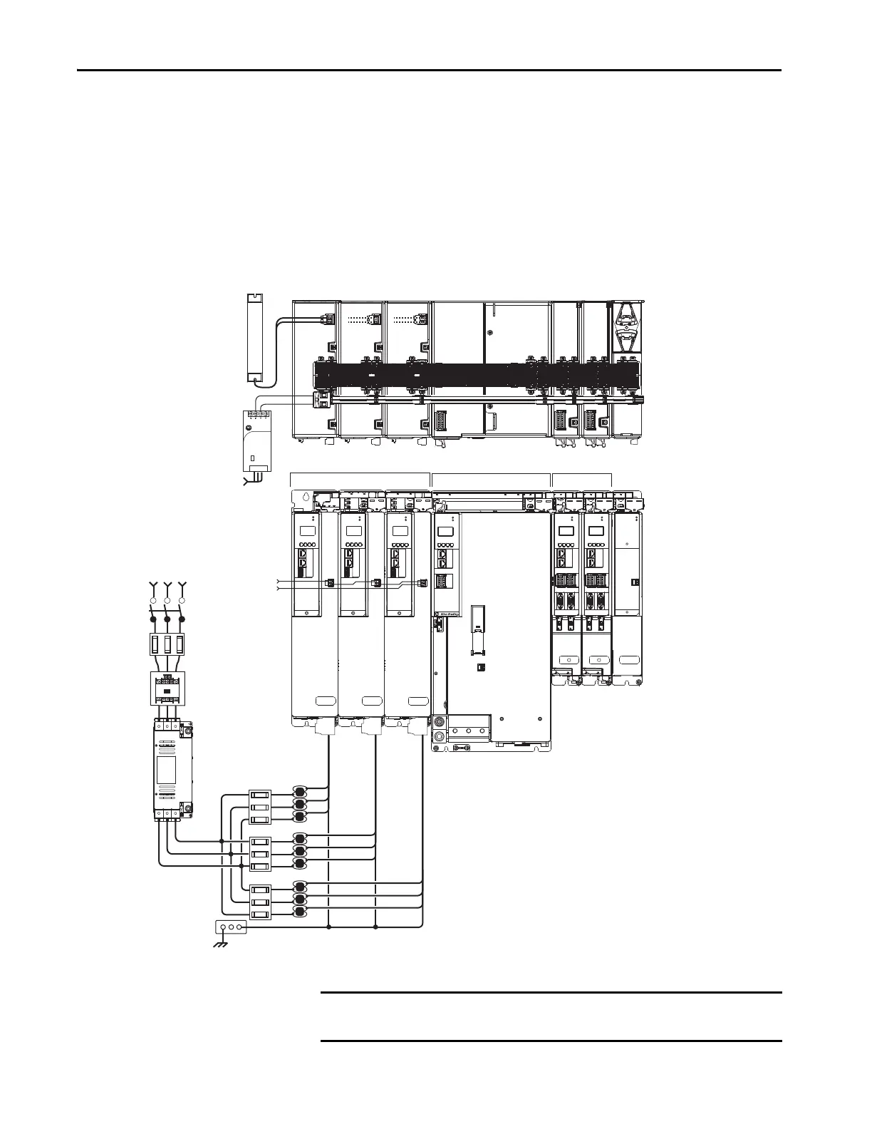
Multiple DC-Bus Power Supply Configuration Example
In this example, three DC-bus (converter) power supplies all receive AC input
power and feed the inverter modules for increased output power.
Contactor enable relays from each of the DC-bus power supplies are wired in
series to protect the DC-bus power supply in the event of shutdown fault
conditions.
Figure 2 - Multiple DC-bus Power Supply Installation
DC+
SH
DC+
SH
1606-XL
Power Supply
Input
Allen-Bradley
MOD
NET
MOD
NET
MOD
NET
2
1
1
4
I/O
2
1
2
1
UFB-A UFB-B
UFB-A UFB-B
D+
D-
D+
D-
D+
D-
MF-A MF-B MF-A MF-B
D+
D-
DC+
SH
MOD
NET
2
1
1
4
I/O
MOD
NET
2
1
1
4
I/O
MOD
DC BUS
MODULE
STATUS
19
8
16
19
8
16
1
I/O-A
6
510
1
I/O-B
6
510
1
I/O-A
6
510
1
I/O-B
6
510
SB+/NC
NC
S1A
SCA
S2A
SB-
NC
NC
SB+/NC
NC
S1A
SCA
S2A
SB-
NC
NC
MOD
NET
2
1
1
I/O
6
5
10
MBRK
+
-
21mm (4 AWG-250 kcmil)
15-20 Nm (132-177 lbin)
2
W V U
19
8
16
SB+/NC
NC
S1A
SCA
S2A
SB-
NC
NC
Bulletin 2198
Shunt Module
(optional component)
1606-XLxxx
24V DC Control Power
(customer-supplied)
AC Input Power
Kinetix 5700 Servo Drive System
(front view)
Kinetix 5700 Servo
Drive System (top view)
Circuit
Protection
Bonded Cabinet
Ground Bus
1321-3R80-B
Line Reactors
(required components)
2198-P208 DC-bus Power Supplies
Single-axis Inverter
Dual-axis Inverters
Capacitor
Module
Bulletin 2198 shared-bus
connection system for DC-bus
and 24V DC control power.
Shared DC-bus Power
Shared 24V Control Power
(24V shared-bus connection
system is optional)
Magnetic Contactor
(M1) Control String
Line Disconnect
Device
324…528V AC
Three-phase
Input Power
Magnetic (M1)
Contactor
2198-DBR200-F
AC Line Filter
(required for CE)
Circuit
Protection
IMPORTANT When two or three DC-bus power supplies are wired together in the same
drive cluster, they must all be catalog number 2198-P208.
 Loading...


