Rockwell Automation Publication 2198-UM002G-EN-P - February 2019 343
Interconnect Diagrams Appendix A
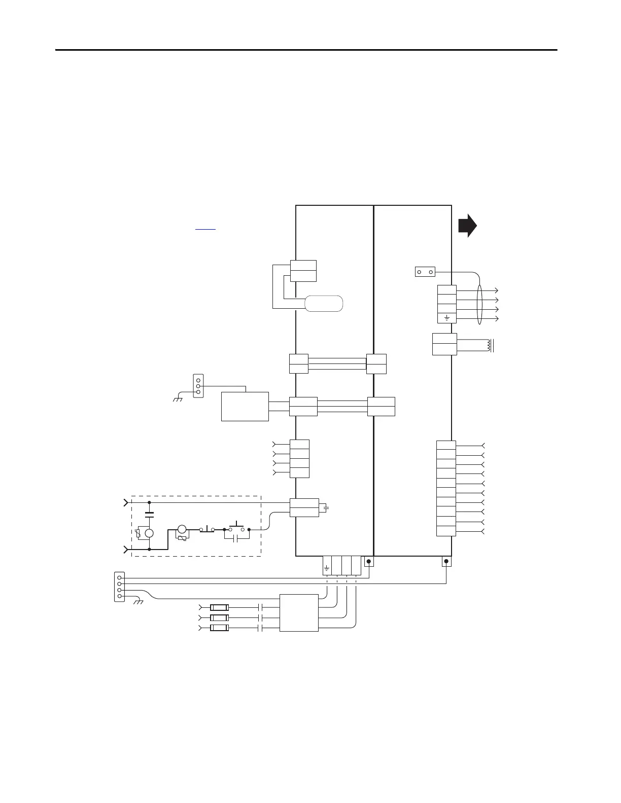
Power Wiring Examples
You must supply input power components. The three-phase line filter is wired
downstream of the circuit protection devices. Each drive module includes the
appropriate DC-bus link and connector set. The 24V supply can be jumpered
from drive-to-drive by using discrete wires or the shared-bus connection
system.
In this example, the inverter drives and optional accessory modules are
downstream of a single 2198-Pxxx DC-bus power supply.
Figure 166 - DC-bus Power Supply (single converter) Configuration
24V_COM
+24V
2
1
24V_COM
+24V
DC+
DC-
DC+
DC-
DC+
SH
1
2
3
4
5
6
7
8
9
10
U
V
W
4
3
2
1
L3 L2 L1
EN+
EN–
CONT EN+
CONT EN–
IN1
COM
IN2
SHLD
1
2
3
4
IN1
COM
IN2
SHLD
COM
IN3
COM
IN4
COM
SHLD
MBRK -
MBRK +
MBRK -
MBRK +
2
1
324…528V AC rms
Three-phase Input
Notes 1, 2
Bonded Cabinet
Ground Bus *
Control Power
(CP) Connectors
Three-phase Input
(IPD) Connector
2198-DBRxx-F
Three-phase
AC Line Filter
Note 5
* Indicates User Supplied Component
Chassis
Customer Supplied
+24V DC
Power Supply *
Refer to table on page 341
for note information.
DC Bus
(DC) Connectors
2198-Pxxx
DC-bus Power Supply
2198-Sxxx -ERSx or
2198-Dxxx -ERSx
Inverter
PE Ground
Note 11
Contactor Enable
(CED) Connector
Note 18
Refer to Attention statement (Note 17).
STOP *
PE Ground
Note 11
Bonded Cabinet
Ground Bus *
Shunt Power
(RC) Connector
Internal Shunt
Note 14
START *
CR1 *
CR1 *
CR1 *
M1 *
Notes 13,18
24V AC/DC
50/60 Hz
Grounding Screws/Jumpers
Note 15
Circuit
Protection*
Note 2
Motor Brake
(BC) Connector
Three-phase
Motor Power
Connections
Notes 8,19
Motor Power
(MP) Connector
Cable Shield
Clamp
Digital Input
(IOD) Connector
Motor Brake
Connections
Note 8
Digital Input
Connections
Note 8
Additional Inverters or
Accessory Modules
Note 7
Digital Input
(IOD) Connector
Digital Input
Connections
Note 9
M1
Contactor
Note 13
Note 8
2198-TCON-24VDCIN36
24V Input Power
Wiring Connector
2198-xxxx-P-T
T-connectors
and Bus Bars
 Loading...


