150 Rockwell Automation Publication 2198-UM002G-EN-P - February 2019
Chapter 5 Connect the Kinetix 5700 Drive System
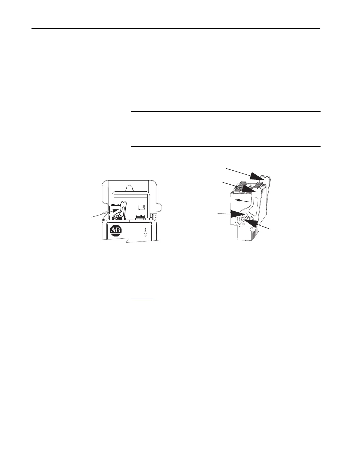
2198-xxxx-ERS4 and 2198-xxxx-ERS3 (series B) Connector Plugs
The safety and digital-input connector plugs have two locking leavers that you
push in a clockwise direction as you insert the plugs into the drive connector.
This is the locked position. Rotate the leavers counter-clockwise (open
position) to release the connector plugs. This applies to 2198-RPxxx
regenerative bus supply and 2198-xxxx-ERS4 and 2198-xxxx-ERS3 (series B)
single-axis and dual-axis inverters.
Figure 98 - 2198-xxxx-ERS4 and 2198-xxxx-ERS3 (series B) Connector Plugs
Wire the Safe Torque-off Connector
For the hardwired safe torque-off (STO) connector pinouts, feature
descriptions, and wiring information, refer to Chapter 9 beginning on
page 305
.
IMPORTANT Push the locking leavers clockwise into the locked position as you insert
the (STO and IOD) connector plugs. Failure to do this can result in the
connector plugs pulling out of the drive connector during normal
operation.
Locking Leavers in
Locked Position
Locked Position
(rotated clockwise)
Kinetix 5700 Inverter
Safety or Digital Inputs Connector Plug
(safety connector plug is shown)
Open Position
(rotated counter-clockwise)
Push to Lock
Push to Lock
Push to Unlock
Safety (STO) Connector Plug
 Loading...


