Rockwell Automation Publication 2198-UM002G-EN-P - February 2019 219
Configure and Start the Kinetix 5700 Drive System Chapter 6
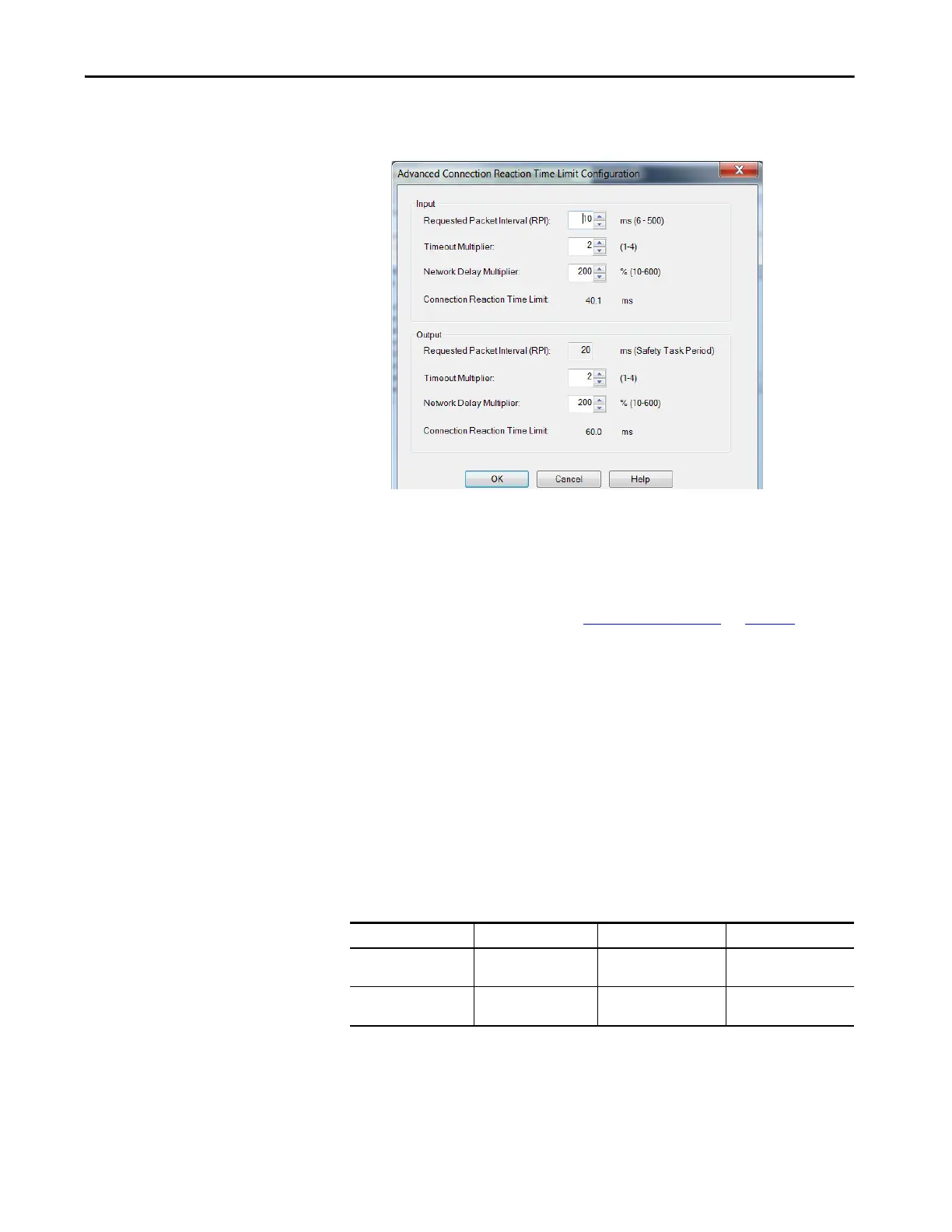
The Advanced Connection Reaction Time Limit Configuration dialog
box appears.
Analyze each safety channel to determine the appropriate settings. The
smallest Input RPI allowed is 6 ms. Selecting small RPI values consumes
network bandwidth and can cause nuisance trips because other devices
cannot get access to the network.
For more information about the Advanced Connection Reaction Time
Limit Configuration, refer to Additional Resources
on page 13 for the
appropriate user manual for your GuardLogix or Compact GuardLogix
controller.
9. Click OK to close the Advanced dialog box.
10. Click Apply to save the Safety category parameters.
Continue Inverter Configuration
After you’ve established your Kinetix 5700 inverters in the Logix Designer
application, the feedback options need to be defined for each axis. Each
physical axis supports motor and auxiliary feedback.
Table 116 - Kinetix 5700 Feedback Axis Summary
Follow these steps to configure the axes for your Kinetix 5700 drive system.
1. Right-click the 2198-xxxx-ERS4 inverter you just created and choose
Properties.
Kinetix 5700 Inverter Inverter Cat. No. Motor Feedback Auxiliary Feedback
Single-axis Inverters
2198-Sxxx-ERS3 or
2198-Sxxx-ERS4
1 (axis 1) 1 (axis 2)
Dual-axis Inverters
2198-Dxxx-ERS3 or
2198-Dxxx-ERS4
2 (axis 1 and 3) 2 (axis 2 and 4)
 Loading...


