106 Rockwell Automation Publication 2198-UM002G-EN-P - February 2019
Chapter 4 Connector Data and Feature Descriptions
Motor Feedback Connector Pinouts
These connector pinouts apply to the single-axis and dual-axis inverter.
Table 42 - DSL Feedback Connector
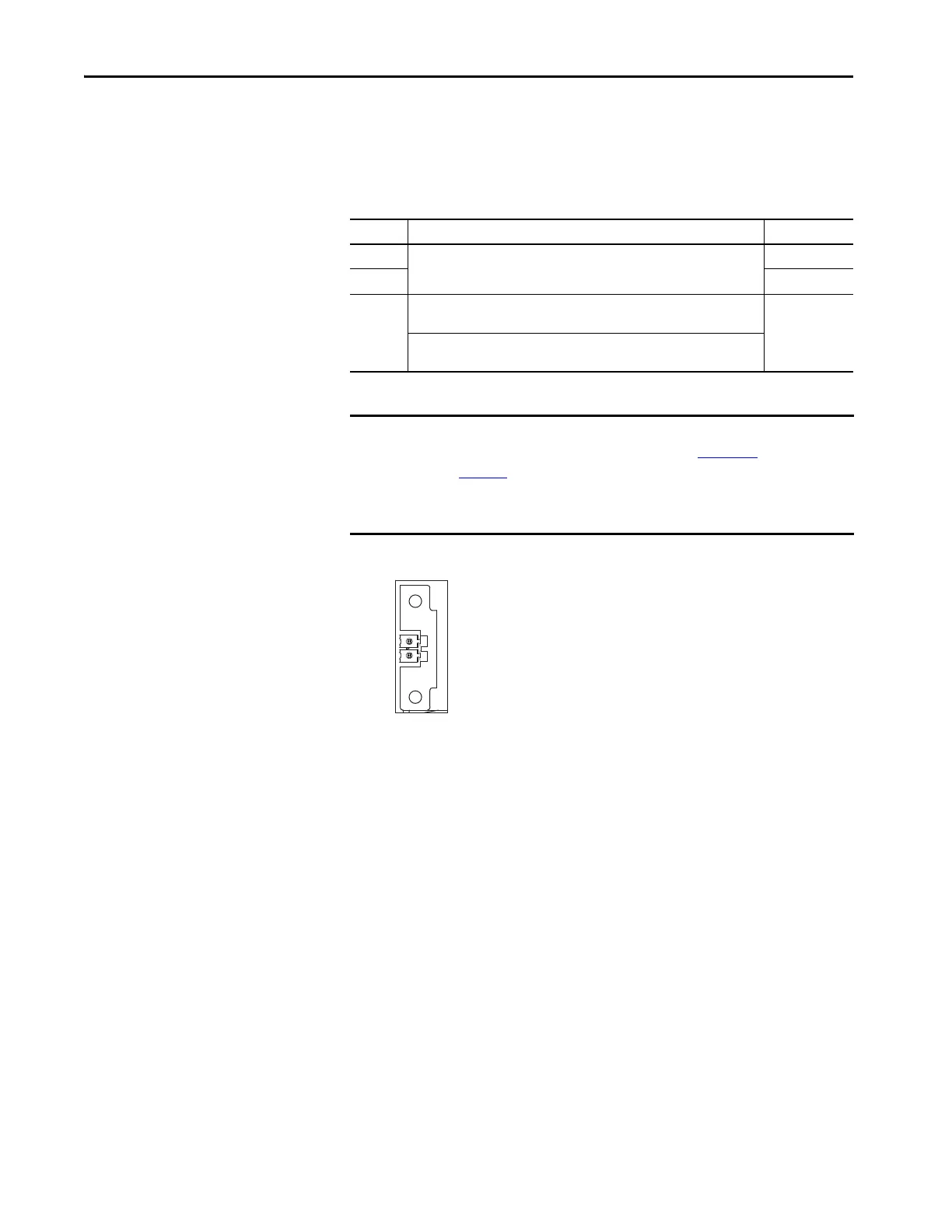
Figure 63 - Pin Orientation for 2-pin DSL Feedback (MF) Connector
MF Pin Description Signal
1
Bidirectional data and power for digital encoder interface
D+
2D–
SHIELD
Cable shield and grounding plate (internal to 2198-KITCON-DSL connector kit)
termination point.
SHIELD
Cable shield and shield clamp (internal to 2198-H2DCK converter kit) termination
point
IMPORTANT Drive-to-motor power cables must not exceed 90 m (295 ft), depending on
feedback type and overall system design. See Appendix D
, beginning on
page 401
, for more information.
System performance was tested at these cable length specifications. These
limitations also apply when meeting CE requirements.
Pin 1
Pin 2
 Loading...


