GEDRAFT LOGIQ P9/P7
D
IRECTION 5604324, REVISION 11 DRAFT (JANUARY 24, 2019) SERVICE MANUAL
Chapter 5 - Components and Functions (Theory) 5-7
5-2-4-1 Front USB
Customer use and Service port connected to USB controller via USB Hub.
NOTE: Front USBs are non-isolated port and not fit to connect external powered USB Devices.
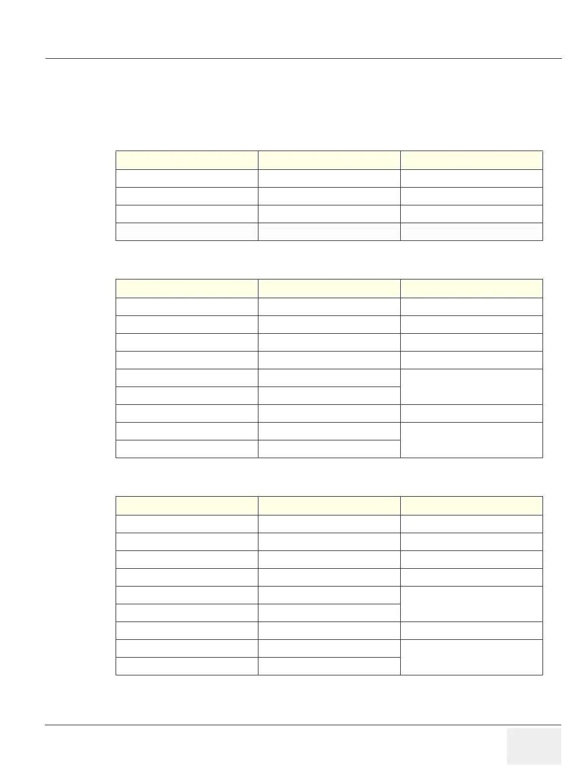
Table 5-2 USB Connectors(on OPIO for R1 to R2.5)
Table 5-3 USB Connectors(on OPIO for R3)
Table 5-4 USB Connectors (on LCD monitor)
5-2-4-2 Rear USB and LAN
2 USB ports and a LAN port are integrated in a connector
Pin No Output Signal Description
1 VCC USB Power Supply
2 - Data USB Data (-)
3 + Data USB Data (+)
4 GND USB Power Ground
Pin No Output Signal Description
1 VCC USB Power Supply
2 - Data USB Data (-)
3 + Data USB Data (+)
4 GND USB Power Ground
5 USB_SSRX-
Receive signal differential pairs for the
Super speed USB data
6 USB_SSRX+
7 GND USB signal Ground
8 USB_SSTX-
Transmit signal differential pairs for the
Super speed USB data
9 USB_SSTX+
Pin No Output Signal Description
1 VCC USB Power Supply
2 - Data USB Data (-)
3 + Data USB Data (+)
4 GND USB Power Ground
5 USB_SSRX-
Receive signal differential pairs for the
Super speed USB data, Not supported
6 USB_SSRX+
7 GND USB signal Ground
8 USB_SSTX-
Transmit signal differential pairs for the
Super speed USB data, Not supported
9 USB_SSTX+
 Loading...


