GERAFT LOGIQ P9/P7
D
IRECTION 5604324, REVISION 11 DRAFT (JANUARY 24, 2019) SERVICE MANUAL
8-152 Section 8-29 - Replacement of Peripheral Cable Assy
8-29-2-5 Installation Procedure
Parts to be installed in reverse order of removal. But, refer to below procedure for cable ties.
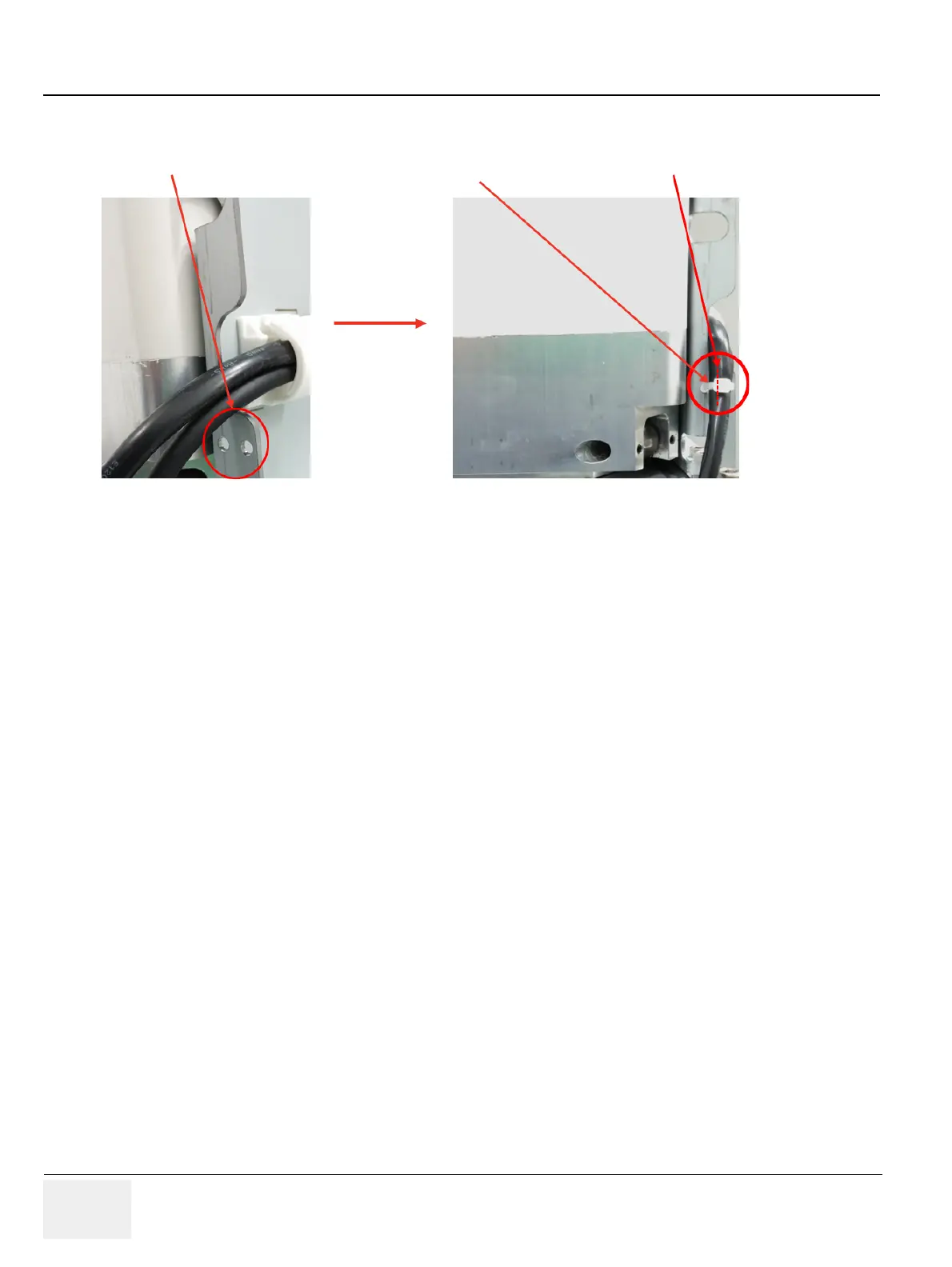
Figure 8-179 Tie cables with the tie through the holes
8-29-2-6 Functional Check
Test 1: Print an image by pressing the button P1 on the operator panel. (P1 key should be configured
correctly. Refer to section 3-8-4 Adding Printer to the system)
Verify1: - Verify that image can be printed.
Verify2: - Verify that printed image has no distortion as compared the image on screen.
2 holes for fixing cable tie
Cable tie
Align the head of cable tie as shown
 Loading...


