GEDRAFT LOGIQ P9/P7
D
IRECTION 5604324, REVISION 11 DRAFT (JANUARY 24, 2019) SERVICE MANUAL
Chapter 8 - Replacement Procedures 8-117
8-17-17 Installation Procedure - MPI, MCB, MDC, DC4D, HDD, Battery and COM Express
1) Parts to be installed in reverse order of removal.
8-17-18 Functional Check - MPI, MCB, MDC, IO Box
Refer to section 4-4 for Functional Diag Test List
8-17-19 Removal Procedure - MBP assy
1) Remove Nest Box from system.
2) Remove MPI, MCB and IO Box out of Nest Frame
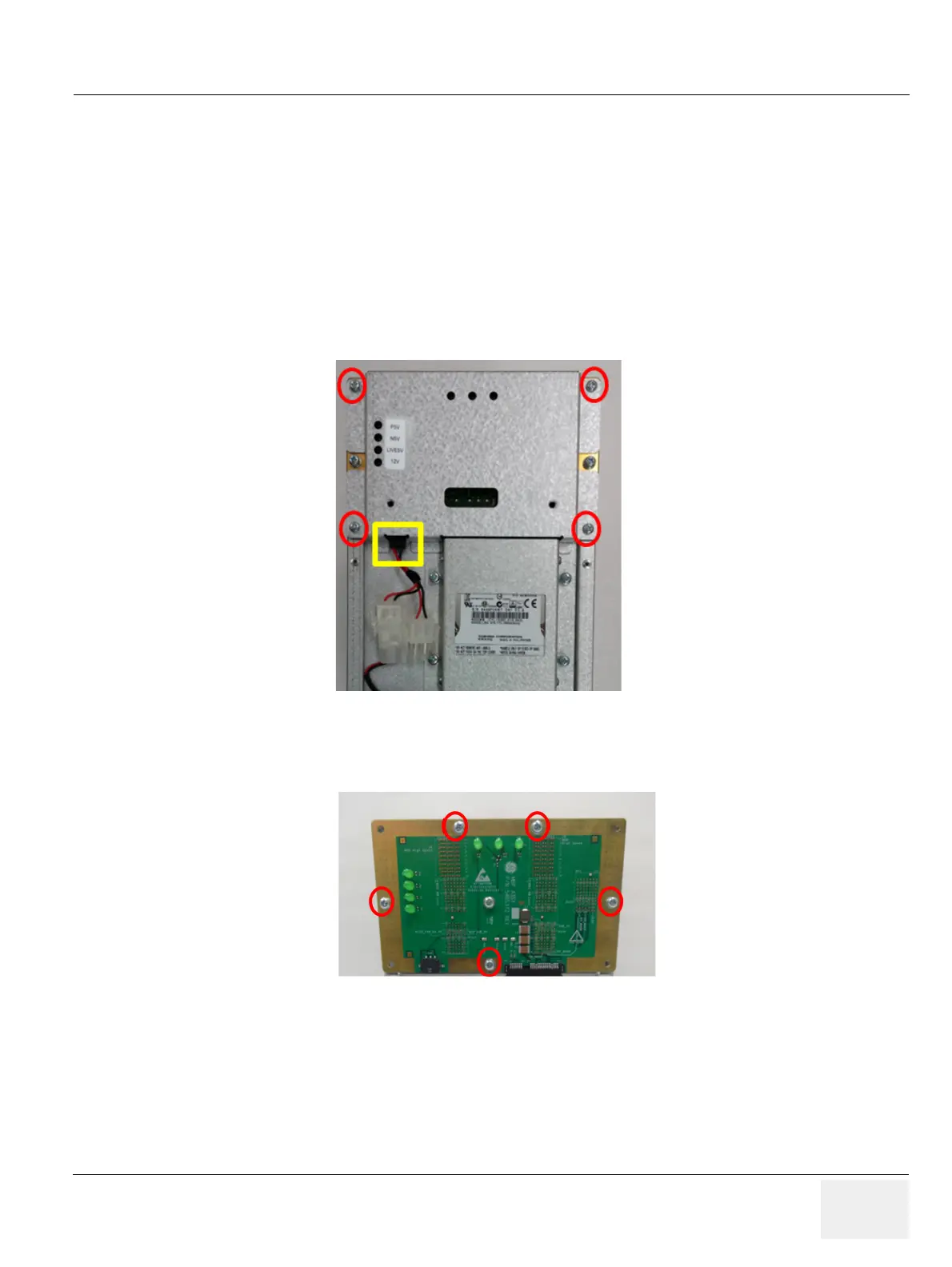
3) Remove 4 screws (Circle) and fan connector (Square).
Figure 8-136 Screw points and connector point to remove MBP
4) Remove 6 screws.
Figure 8-137 Screw points to remove MBP
8-17-20 Installation Procedure - MBP assy
Parts to be installed in reverse order of removal.
8-17-21 Functional Check
Refer to section 4-4 for Functional Diag Test List.
 Loading...


