GERAFT LOGIQ P9/P7
D
IRECTION 5604324, REVISION 11 DRAFT (JANUARY 24, 2019) SERVICE MANUAL
8-122 Section 8-20 - Replacement of Rear Handle
Section 8-20
Replacement of Rear Handle
8-20-1 Manpower
1 Person, 10 minutes.
8-20-2 Tools
Standard Phillips Screwdriver and 6mm Hex Wrench.
8-20-3 Removal Procedure
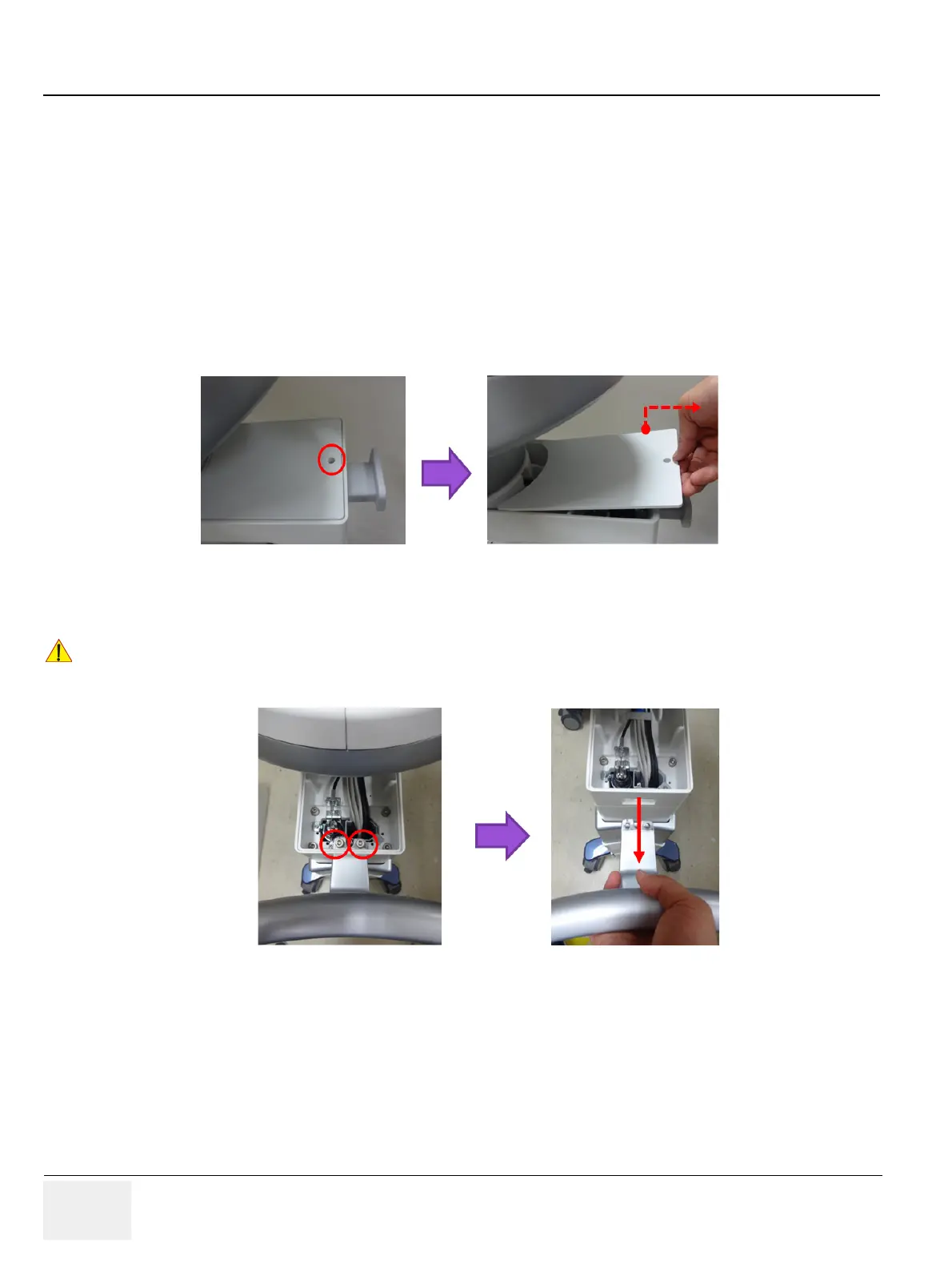
1) Remove 1 screw and remove the Link Arm Top Cover as following figure.
Figure 8-143 Removal of Link Arm Top Cover.
2) Remove 2 Hex screws. Refer to following figure.
Figure 8-144 Hex screw points of Rear Handle
8-20-4 Installation Procedure
Parts to be installed in reverse order of removal.
NOTE: Hex screws should be tightened.
8-20-5 Functional Check
Visual Check only.
!! CAUTION:
Rear Handle will not stay in position without screws. Make sure not to drop the part when
removing/installing Rear Handle
 Loading...


