EasyManuals Logo
Home>GE>Medical Equipment>LOGIQ P7

GE LOGIQ P7 Service Manual

GE LOGIQ P7
602 pages
To Next Page IconTo Next Page
To Previous Page IconTo Previous Page
Page #439 background imageLoading...
Page #439 background image
GEDRAFT LOGIQ P9/P7
D
IRECTION 5604324, REVISION 11 DRAFT (JANUARY 24, 2019) SERVICE MANUAL
Chapter 8 - Replacement Procedures 8-113
8-17-13 Separating DC4D Unit from IO BOX
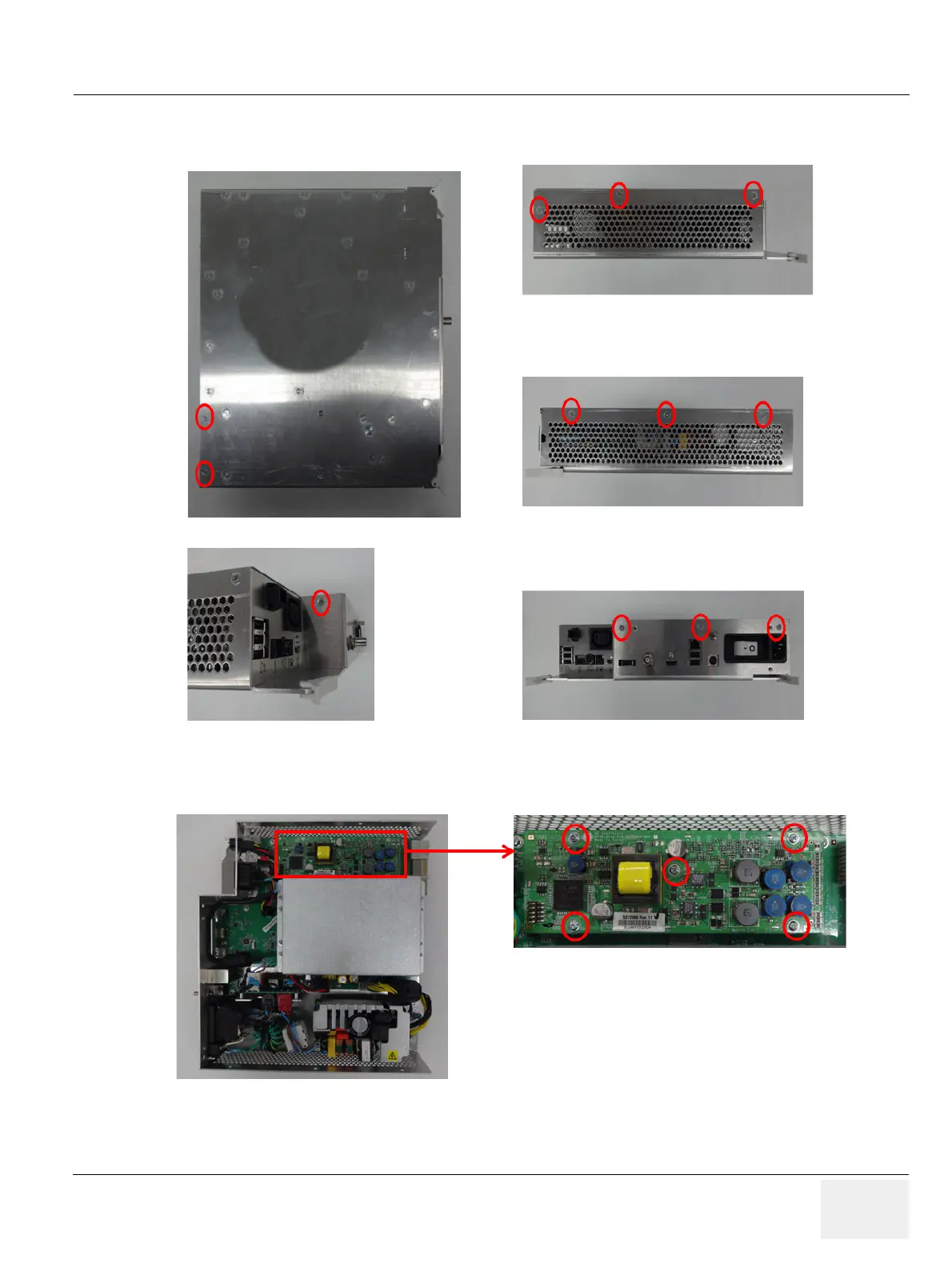
1) Unscrew 12 screws to remove the IO BOX Cover.
Figure 8-128 Screw points of IO BOX cover
2) Unscrew five screws to remove the DC4D from the MIO Assy. Refer to following figure.
Figure 8-129 Screw points of DC4D Assy
3) Carefully lift up the DC4D unit.

Table of Contents

Other manuals for GE LOGIQ P7

Questions and Answers:

Question and Answer IconNeed help?

Do you have a question about the GE LOGIQ P7 and is the answer not in the manual?

GE LOGIQ P7 Specifications

General IconGeneral
BrandGE
ModelLOGIQ P7
CategoryMedical Equipment
LanguageEnglish

Related product manuals