GERAFT LOGIQ P9/P7
D
IRECTION 5604324, REVISION 11 DRAFT (JANUARY 24, 2019) SERVICE MANUAL
5-12 Section 5-3 - Power ON Sequence
Section 5-3
Power ON Sequence
Sequence
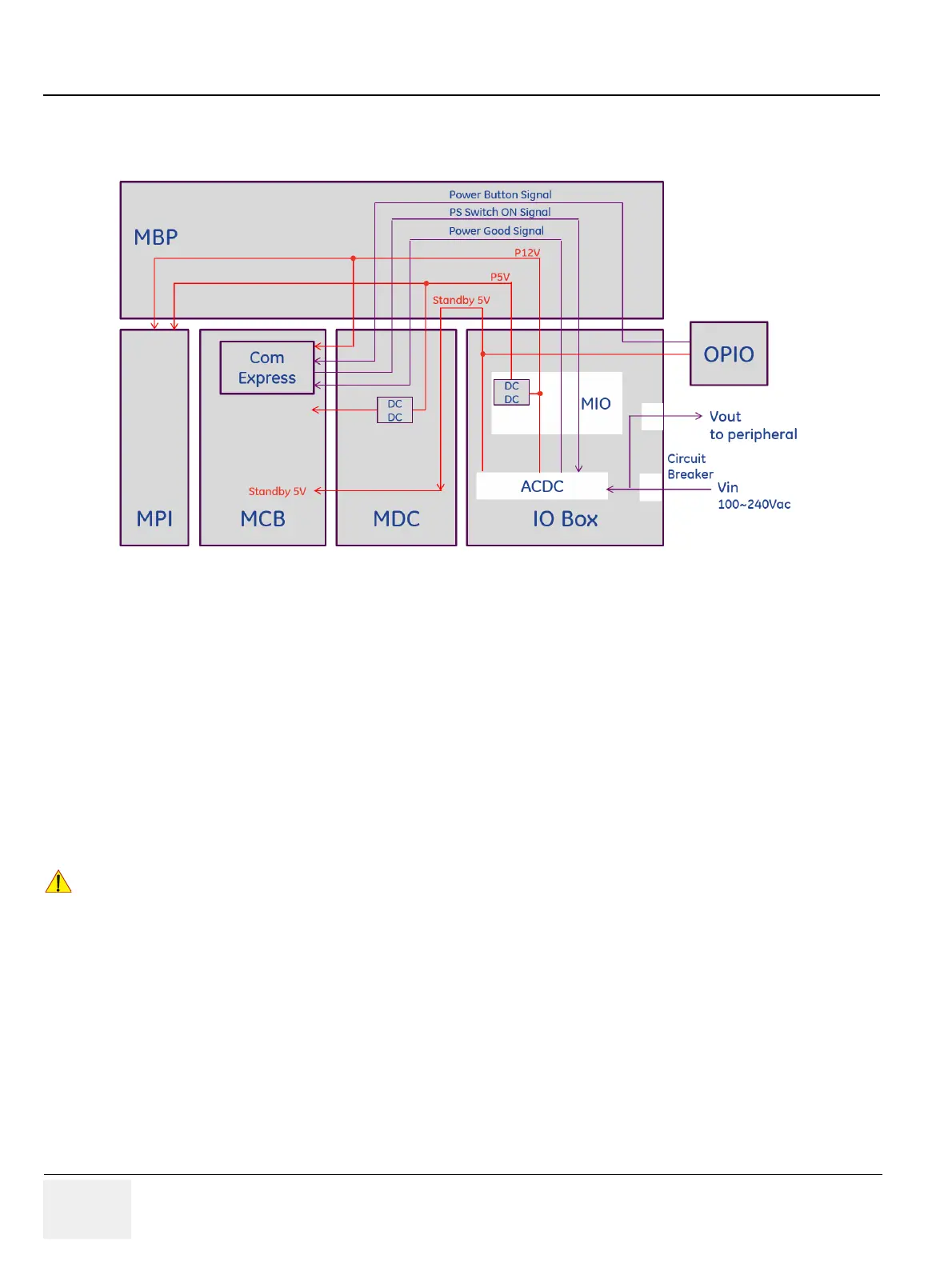
1) Circuit breaker ON
2) AC/DC in IOBOX generates standby 5V
3) Standby 5V is supplied to OPIO, COM Express and each board
4) OPIO generates Button signal
5) COM Express receives the Button signal and generates Power Switch On signal
6) ACDC generates P12V after receiving Power Switch On signal from COM Express.
7) AC/DC route P12V to each board
- AC Power is supplied to BW Printer, after generating P12V
- MIO generates P5V and routes to each board
8) MDC generates LV, HV, SHV to MCB and MPI
Power-ON using Battery is NOT allowed.
 Loading...


