GEDRAFT LOGIQ P9/P7
D
IRECTION 5604324, REVISION 11 DRAFT (JANUARY 24, 2019) SERVICE MANUAL
Chapter 8 - Replacement Procedures 8-95
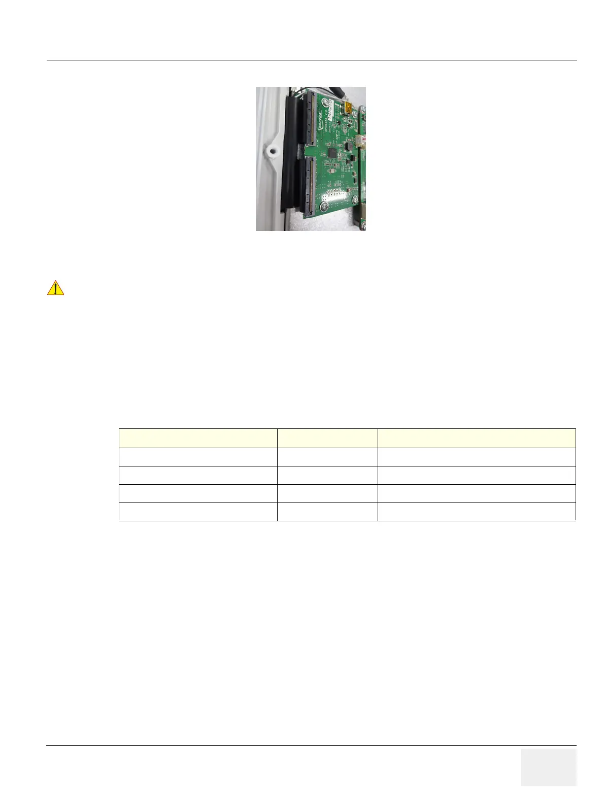
NOTE: Make sure to connect Touch panel connector to hub board as blow figure.
Figure 8-98 Installation of Touch panel connector
NOTE: In some cases, when OPIO is replaced the Windows base system may recognize new OPIO as ‘new’
hardware device.
This could bring Touch Panel graphics to top of main screen resulting to have only the wall paper (ping,
cherry blossom) without touch panel buttons.
When this occurs, go into Windows desktop, and double click “OPIO Position Reset” icon.
Alternatively, go to Windows graphics property manager, and bring SCREEN3 to below SCREEN1.
8-14-5 Functional Check
!! CAUTION:
Make sure not to remain any dust on Glass during OPIO Upper Cover and Touch Screen Assy
installation
Test Refer to Note
System Exterior Visual Check
section 4-3-1
Control panel visual check only
Power On/Off
section 4-3-3
System Integration Checks
section 4-3-5
section 4-3-5-1 OPIO Test only
OPIO Interface Check
section 4-3-8
 Loading...


