GERAFT LOGIQ P9/P7
D
IRECTION 5604324, REVISION 11 DRAFT (JANUARY 24, 2019) SERVICE MANUAL
8-172 Section 8-43 - Replacement of DCWD ASSY
Section 8-43
Replacement of DCWD ASSY
8-43-1 Manpower
1 person, 15 minutes
8-43-2 Tools
Standard Phillips screwdriver.
8-43-3 Removal Procedure
1) Separate MPI assy from MCB and MDC. Refer to the section 8-17-8 Removal Procedure -
Separating MPI and MCB.
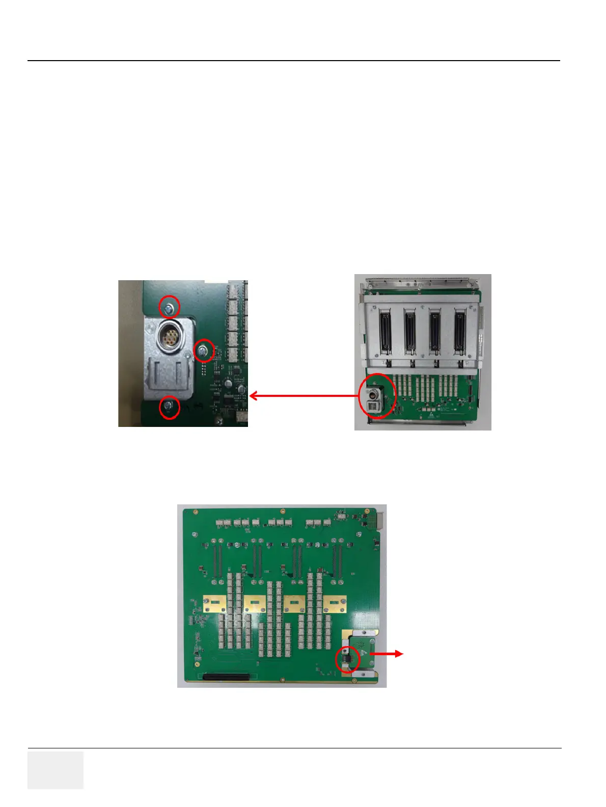
2) Remove 3 screws on MPI assy.
Figure 8-203 DCWD Board screw points
3) Carefully separate DCWD board from MPI assy not to damage the DCWD connector. Refer to
following figure.
Figure 8-204 Position of DCWD board connector
 Loading...


