Controlling Operation and Outputting Data with the Sensor's Standard Parallel Connection
FQ2-S4 User’s Manual
281
8
Controlling Operation and Outputting Data
with a Parallel Connection
• Create the ladder program to control the TRIG and IN5 input signals so that they do not turn ON while the BUSY
signal is ON. If not, a TRIG input error will occur and the ERROR signal will turn ON.
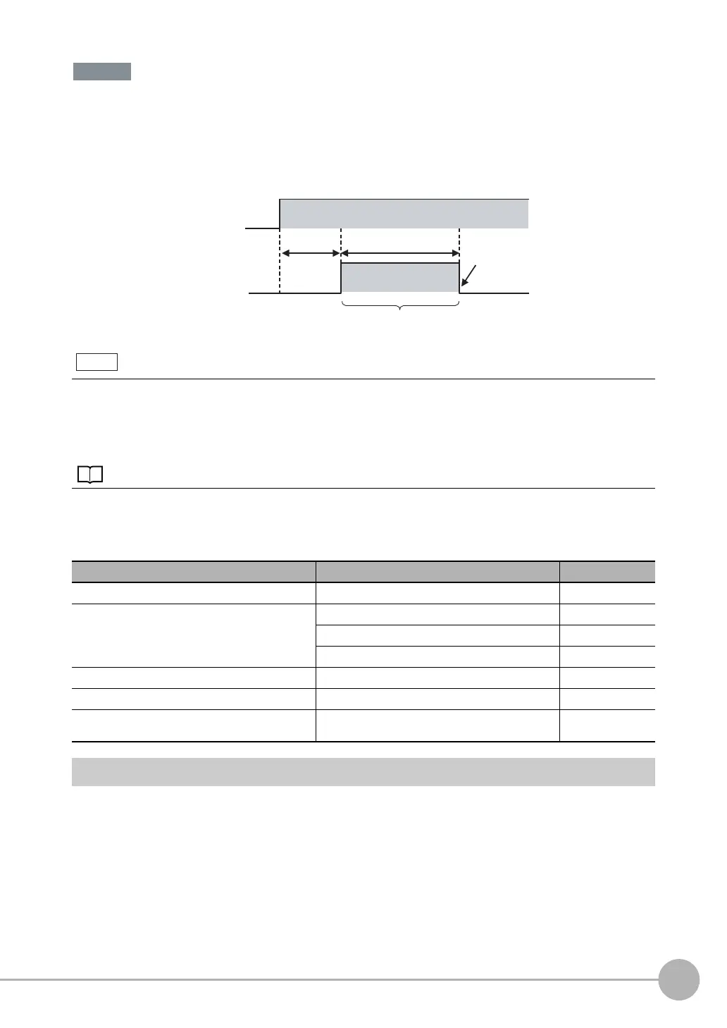
• Operation When the Sensor Power Supply Is Turned ON
The BUSY signal will operate as shown below when the Sensor’s power supply is turned ON.
Create the ladder program in the PLC or other external device so that the BUSY signal is ignored while it turns OFF,
ON, and OFF again for up to 5 s after the power supply is turned ON.
* Depends on the scene data.
Configuring the Operation
The following settings can be selected depending on the system configuration and application.
Setting the Measurement Trigger
The measurement trigger can be chosen from the following two types:
• One-shot measurement: One measurement is performed for each external trigger.
• Continuous measurement: Measurements are performed continuously.
You can mount a Parallel Interface Sensor Data Unit to enable using other signals and increase the number of sig-
nals that you can use with parallel communications.
And in addition to outputting OR judgement results, you can also use a Parallel Interface Sensor Data Unit to output
the judgement results of judgement conditions that you set for parallel output (called parallel judgement output) and
the results of measurement values and expressions for inspection items (called parallel data output).
8-2 Controlling Operation and Outputting Data with a Parallel Interface Sensor Data Unit: p. 302
Type of change Change Reference
Changing the type of measurement trigger Performing continuous measurements p. 283
Changing the output method of the judgement results Obtaining individual judgement results p. 287
Adjust the judgement output timing p. 288
Changing the judgement output ON conditions p. 290
Changing the polarity of the BUSY output Reversing the polarity of the BUSY signal p. 290
Changing the BUSY output condition Adjusting the end timing of the BUSY signal p. 290
Changing the polarity of the output signals (OUT1 to
OUT3)
Reversing the output polarity of OUT1 to OUT3 p. 290
Important
24 V
BUSY
ON
OFF
0 V
1.5 s 3.5 s*
Sensor system is initializing
Turns OFF when the
Sensor is ready for
operation.
Power supply
Note

 Loading...


