PLC Link Connections
FQ2-S4 User’s Manual
385
Connecting through Ethernet
9
Memory Assignments for PLC Link Communications
This section describes the assignments for the Command, Response, and Data Output Areas.
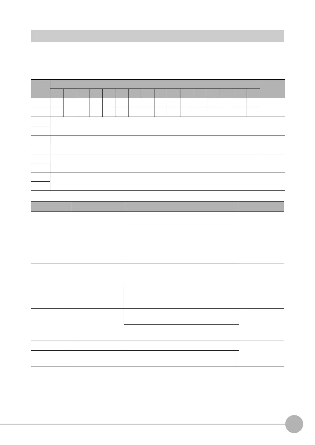
● Command Area
PLC (Master) to Vision Sensor (Slave)
First
word
Bits Contents
15 14 13 12 11 10 9 8 7 6 5 4 3 2 1 0
+0
ERRCLR
Resv Resv Resv Resv Resv Resv Resv Resv Resv Resv Resv Resv Resv Resv EXE Control sig-
nals (32
bits)
+1 Resv Resv Resv Resv Resv Resv Resv Resv Resv Resv Resv Resv Resv Resv Resv
DSA
+2 Command code Command
code (32
bits)
+3
+4 Parameter 1 Parameter
(integer)
+5
+6 Parameter 2 Spare (inte-
ger)
+7
+8 Parameter 3 Spare (inte-
ger)
+9
Signal Signal name Function Application
EXE Control Command
Execution Bit
Turn ON this signal from the PLC to send a control
command for the Vision Sensor to execute.
Command/
response commu-
nications
Turn OFF the EXE signal from the PLC when the
Control Command Completed (FLG) signal from the
Vision Sensor turns ON. (Set the control command
code and parameters before you turn ON this sig-
nal.)
DSA Data Output Request
Bit
Turn ON this signal from the PLC to request data
output. When this signal turns ON, the Vision Sen-
sor outputs data.
Data output after
measurements
Turn OFF the DSA signal from the PLC when the
Data Output Completed (GATE) signal from the
Vision Sensor turns ON.
ERRCLR Clear Error Turn ON this signal to turn OFF the error (ERR) sig-
nal from the Vision Sensor.
Command/
Response Commu-
nications
Turn OFF this signal from PLC when the error (ERR)
signal goes OFF.
Command code Command code This I/O port stores the command code. Command/
Response Commu-
nications
Parameters 1 to
3
Command parameters These I/O ports store the command parameters.

 Loading...


