Outputting Data and Controlling Operation through EtherNet/IP
338
FQ2-S4 User’s Manual
Tag Data Link Setting Methods
This section describes how to set data links for EtherNet/IP.
The communications areas in the PLC for which data links are created to the Sensor are specified as tags and
tag sets, and the connections are set for tag data link communications.
Tags, tag sets, and connections are set from the Network Configurator.
Refer to the following manuals for details on the tag data link settings that are made with the Network
Configurator.
• NJ-series CPU Unit Built-in EtherNet/IP Port User’s Manual (Cat. No. W506)
• CS/CJ-series EtherNet/IP Units Operation Manual (Cat. No. W465)
• CJ-series EtherNet/IP Units Operation Manual for NJ-series CPU Unit (Cat. No. W495)
• To connect the FQ2 to an NJ/CJ-series CPU Unit, install the EDS file that defines the connection information for the
FQ2 in the Network Configurator. Download the EDS file from the OMRON website.
• After tag data links are set, the Vision Sensor will automatically be restarted to enable the settings.
Tags, Tag Sets, and Connection Settings
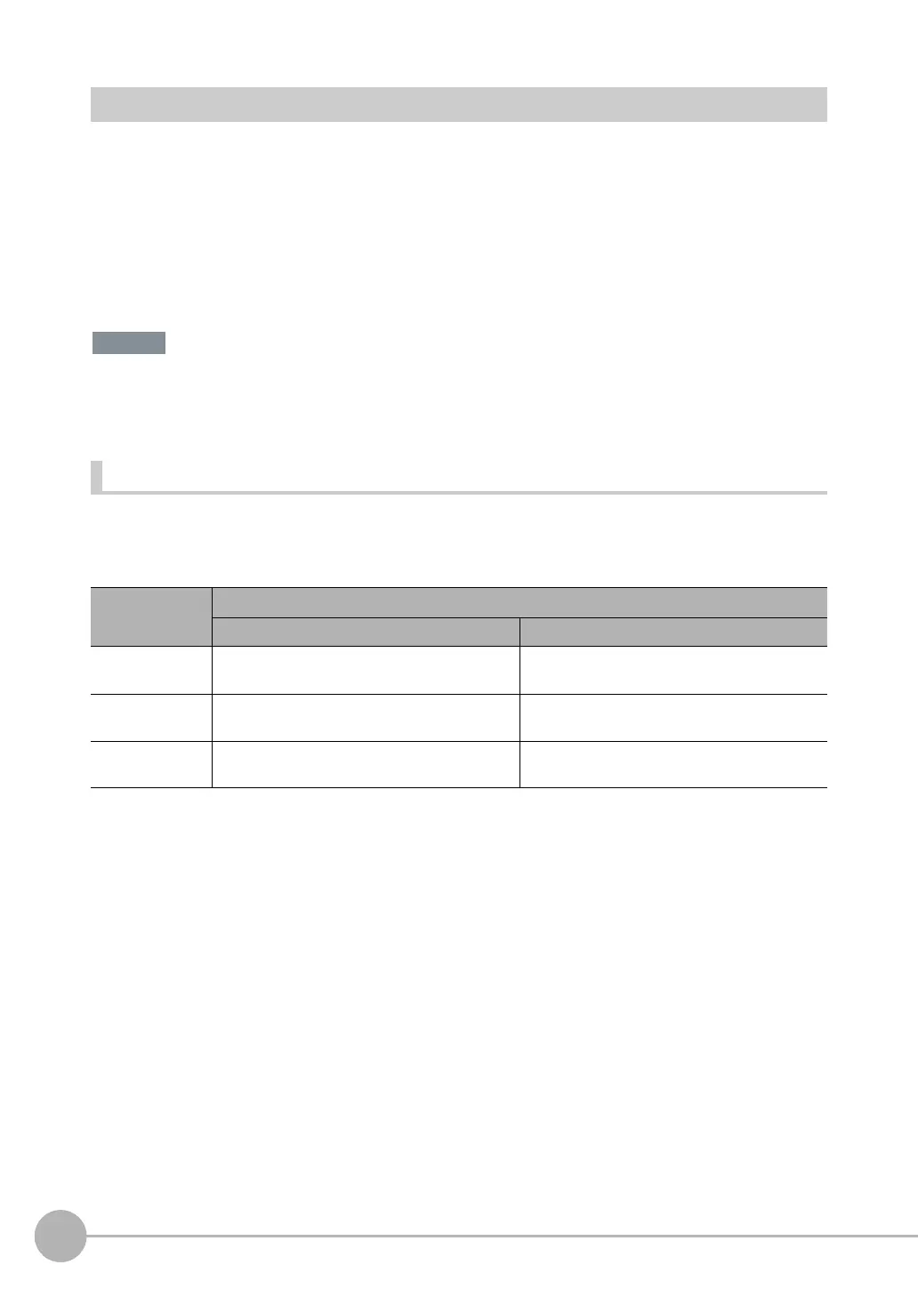
The communications areas in the PLC are set as tag data link connections as shown in the following table.
• Tag and Tag Set Settings in the PLC
*1 Specify the I/O memory address of the first word in the response area.
The output area is assigned immediately after the response area.
If you specify a variable name, the variable is assigned for both the response area and output area.
Refer to Accessing Communications Areas Using Variables with NJ-series Controllers on p. 352 for information on how to access the sig-
nals in the communications areas from the user program when variables are assigned.
Parameter Settings
Command area Response area and output area
Type of tags and
tag set
Output tag set Input tag set
Tag and tag set
names
I/O memory addresses or variable names I/O memory addresses or variable names
*1
Data size 20 bytes 48 to 272 bytes (total size of response area and
output area)
Important

 Loading...


