Installation
FQ2-S4 User’s Manual
2
Installation and Connections
35
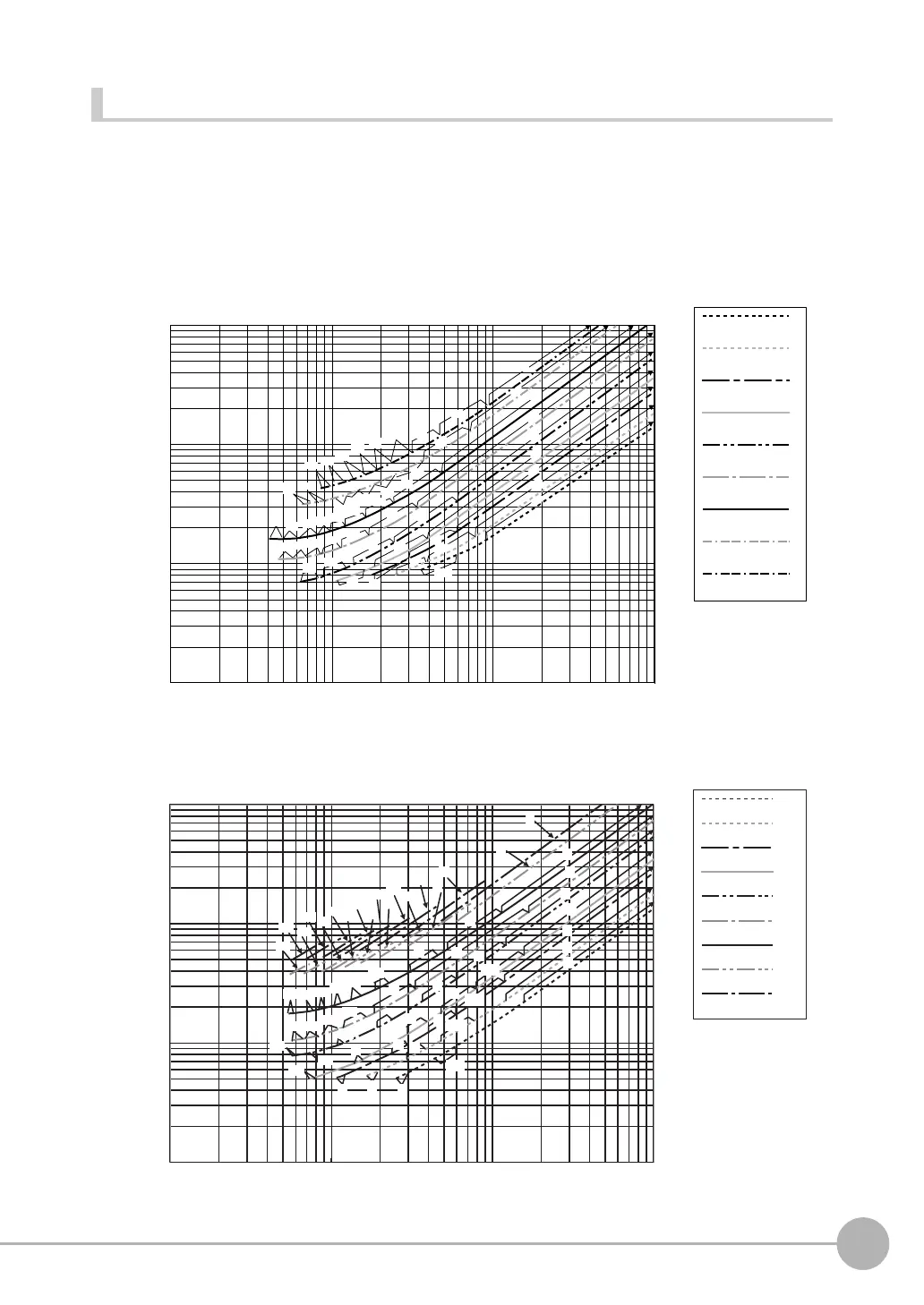
Lens Selection
Use the following optical diagrams to determine the Lens, camera installation distance, and detection range.
Optical Diagrams
The following values are estimates only. Adjustment is required after installing the camera.
3Z4S-LE SV-@@@@H High-resolution, Low-distortion Lenses
3Z4S-LE SV-@@@@V-series Lenses
Camera installation distance (mm)
t: Macro ring
Examples
t0: Macro ring is
not required.
t5: A 5-mm macro
ring is required.
Y axis of field of view (mm)
10
100
1000
10000
1000100101
SV-0614H
3Z4S-LE
SV-0814H
SV-1214H
SV-1614H
SV-2514H
SV-3514H
SV-5014H
SV-7525H
SV-10028H
t0
t5
t10
t15
t20
t25
t30
t40
t50
t0
t5
t10
t15
t20
t25
t30
t0
t2
t5
t10
t15
t2
t5
t0
t1
t2
t0
t0.5
t1
t0
t0.5
t50
t40
t25
t15
t10
t5
t0
t50
t40
t30
t20
t25
t15
t10
t0
t5
t30
t20
t0
Camera installation distance (mm)
t: Macro ring
Examples
t0: Macro ring is
not required.
t5: A 5-mm macro
ring is required.
Y axis of field of view (mm)
SV-0614V
3Z4S-LE
SV-0813V
SV-1214V
SV-1614V
SV-2514V
SV-3518V
SV-5018V
SV-7527V
SV-10035V
10
100
1000
10000
100010010
1
t2
t5
t10
t15
t20
t25
t30
t40
t0
t1
t5
t10
t15
t20
t25
t0
t1
t2
t5
t10
t15
t25
t0
t0.5
t1
t2
t5
t10
t0
t0.5
t1
t2
t5
t0
t0.5
t1
t2
t0
t0.5
t1
t0
t0
t5
t10
t15
t20
t25
t30
t40
t50
t0
t5
t10
t15
t20
t25
t30
t40
t50

 Loading...


