R01UH0823EJ0100 Rev.1.00 Page 1745 of 1823
Jul 31, 2019
RX23W Group 51. Electrical Characteristics
Note 1. P41 and P47: Set AVCC0 to the same voltage as VCC.
If conditions other than those above are applicable, those listed below apply.
While VCC > 2.4 V: AVCC and VCC can be set independently when AVCC0 ≥ 2.4 V
While VCC ≤ 2.4 V: AVCC and VCC can be set independently when AVCC0 ≥ VCC
Note 2. When powering on the VCC and AVCC0 pins, power them on at the same time or the VCC pin first and then the AVCC0 pin.
Note 3. Set VCC_RF and AVCC_RF to the same voltage as VCC.
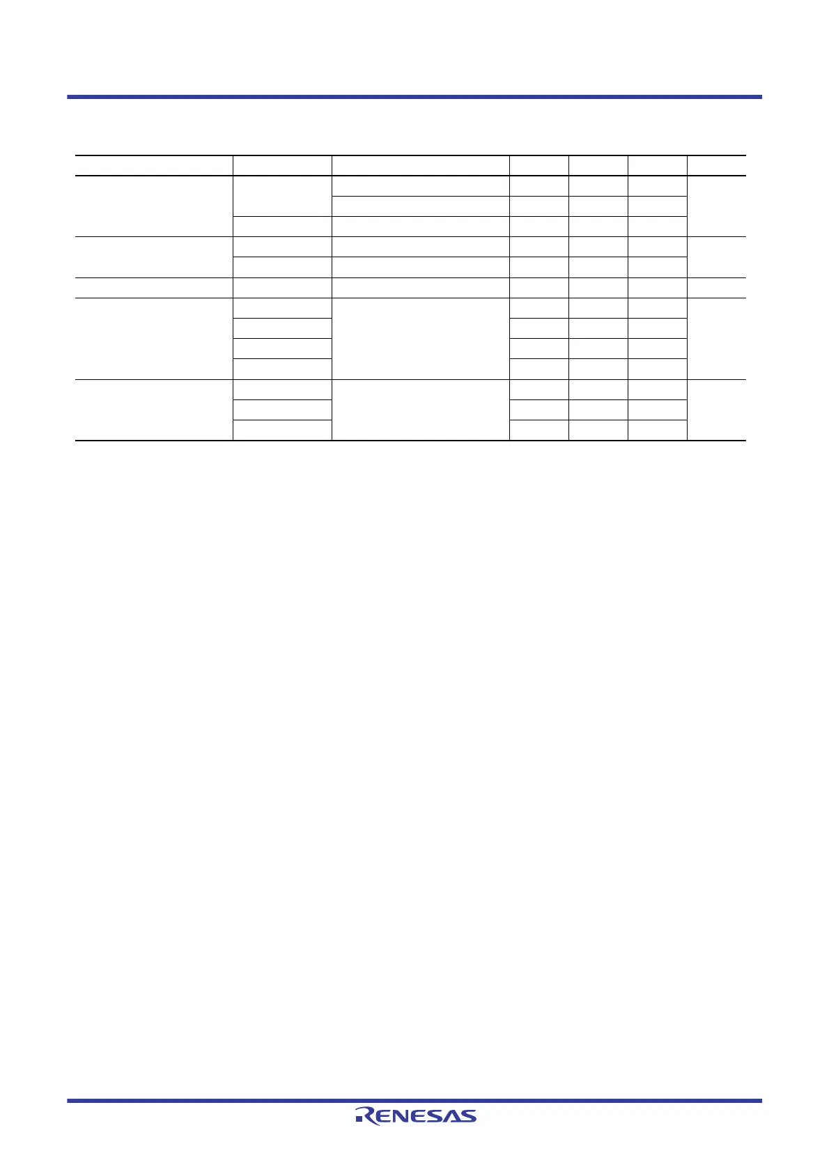
Table 51.2 Recommended Operating Voltage Conditions
Item Symbol Conditions Min. Typ. Max. Unit
Power supply voltages VCC
*1, *2, *3
When USB is not used 1.8 — 3.6 V
When USB is used 3.0 — 3.6
VSS — 0 —
USB power supply voltages VCC_USB When USB regulator is not used — VCC — V
VSS_USB — 0 —
VBATT power supply voltage VBATT 1.8 — 3.6 V
Analog power supply voltages AVCC0
*1, *2
1.8 — 3.6 V
AVSS0 — 0 —
VREFH0 1.8 — AVCC0
VREFL0 — 0 —
BLE power supply voltages VCC_RF
*3
1.8 — 3.6 V
AVCC_RF
*3
1.8 — 3.6
VSS_RF — 0 —

 Loading...


