Home
Siemens
Servo Drives
SINAMICS S210
Siemens SINAMICS S210 User Manual
5
of 1
of 1 rating
768 pages
Give review
Manual
Specs
To Next Page
To Next Page
To Previous Page
To Previous Page
Loading...
6.8.1.3
Commissioning step 2
Parameterization
Adapt the required settings in the "Parameterization" tab.
Figure 6-22
Configuring the parameterization
Commissioning and diagnostics in the Web server
6.8 Safety settings
SINAMICS S210 servo drive system
140
Operating Instructions, 12/2017, A5E41702836B AA
141
143
Table of Contents
Default Chapter
4
Qualified Personnel
4
Preface
5
Technical Support
6
Use of Openssl
6
Table of Contents
7
Warning Notice System
4
1 Fundamental Safety Instructions
13
General Safety Instructions
13
Equipment Damage Due to Electric Fields or Electrostatic Discharge
19
Warranty and Liability for Application Examples
20
Industrial Security
21
Residual Risks of Power Drive Systems
22
2 Description
23
Correct Usage
23
Typical Applications
23
System Overview
24
System Components and Accessories
25
Converter
26
MOTION-CONNECT Cable (OCC Cable)
26
Motor
26
The Scope of Supply for the System Components
26
Cooling
27
Degree of Protection
27
Dynamic Versions
27
Motor
27
Power Range
27
Bearing Version
28
Encoder
28
Holding Brake
28
Shaft Extension (IEC 60072-1)
28
Rating Plate
29
Communicating with the Controller Via PROFINET
30
Control Mode
30
Converter
30
Integrated Braking Resistor
30
Integrated Safety Functions
30
Commissioning, Diagnostics and Data Backup
31
Rating Plate and Information Plate
31
Information Plate of the Converter
32
Connection Systems
33
Motor-Converter Combinations
34
Optional Accessories
35
3 Configuring
37
EMC-Compliant Installation of a Machine or System
37
Control Cabinet
37
Cables
38
Cable Routing Inside the Cabinet
38
Routing Cables Outside the Control Cabinet
39
Routing Converter Cables Inside and Outside a Control Cabinet
39
Electromechanical Components
40
Requirements Relating to Shielded Cables
40
Surge Voltage Protection Circuit
40
Permissible Line Supplies and Connection Options
41
Converter Operated on an IT System
41
Connection Options, 230 V Devices
42
Basic Connection Options
42
Connection Examples and Cable Cross-Sections
44
Connection Example for 400 V 3 AC
45
Configuring the Motor
46
Configuration Sequence
46
Motion Control
46
General Configuring Procedure
46
Clarification of Type of Drive
47
Limiting Characteristic for Synchronous Motors 1FK2
48
Specification of the Supplementary Conditions and Integration into the Automation System
48
Definition of the Load, Calculation of the Maximum Load Torque and Determination of the Motor
48
Duty Cycles with Constant on Duration
49
S1 Duty (Continuous Operation)
49
Motor Selection for a Duty Cycle with Constant Switch-On Duration
50
Free Duty Cycle
51
Example of Free Duty Cycle
51
Motor Selection for Duty Cycle
52
Specification of the Motor
53
Configuring the External Braking Resistor
54
When Do You Require an External Braking Resistor?
54
Requirements Placed on the External Braking Resistor
55
Resistance Data for an External Braking Resistor
55
Examples of Suitable External Braking Resistors from a Third Party
55
Connecting the External Braking Resistor
55
Setting the Temperature Monitoring of the External Braking Resistor
56
Establishing Communication of the Converter with the Controller
57
4 Safety Functions Integrated in the Drive
59
Overview of Safety Integrated Functions
59
Basic Functions
59
Safe Torque off (STO)
60
Functional Features
60
Basic Functions
60
Sequence Diagram
61
Selecting/Deselecting "Safe Torque Off"
61
Safe Brake Control (SBC)
63
Applications
63
Safe Stop 1 (SS1, Time-Controlled)
65
SS1 with OFF3 (SS1-T)
65
Flow Diagram SS1 with OFF3 (SS1-T)
66
Shutting down the Motor with SS1 Active
66
SS1 with External Stop (SS1E)
67
Flow Diagram SS1 with External Stop (SS1E)
68
Setting the Delay Time for SS1
68
Configuring the Safety Functions
70
Selection Via F-DI
70
Selection Via Profisafe
70
Selection Via PROFINET
70
Responses to Safety Faults
71
Stop Responses
71
Internal Event
71
Response to a Discrepancy When STO Is Active
73
Drive Response
73
Switching the Motor on Again
73
Acknowledging an Internal Event
73
System Properties
75
Response Times of the Basic Functions
75
Note for Understanding the Following Tables
75
Control of the Basic Functions Via Terminals
75
Control of the Basic Functions Via Profisafe
76
Response Times When Controlling Via Profisafe
76
PFH Values
76
Acceptance - Completion of Commissioning
77
What Is an Acceptance?
77
Acceptance Test of the Machine or Plant
77
Acceptance Test of the Converter
77
Persons Authorized for Acceptance
78
When Do You Have to Conduct an Acceptance Test of the Converter?
78
What Does the Acceptance Test for the Converter Consist Of?
78
STO Acceptance Test
80
Select STO
80
Deselect STO
80
SBC Acceptance Test
81
Switch on Motor
81
Select SBC
81
SS1 Acceptance Test
82
Select SS1
82
Deselect SS1
82
Functional Safety
83
Machinery Directive
84
5 Installing
85
Safety Instructions
85
Installing the Motor
86
Checklists Prior to Assembly
86
Mounting Instructions for the Motor
87
Tightening Torques for Fastening Bolts
87
Fitting Output Elements
88
Mounting and Removing Output Elements
88
Installing the Converter
89
Installation Conditions
89
Dimension Drawings and Drilling Dimensions
90
Distances to Cabinet Walls and Other Components
90
Connecting the Converter and the Motor
91
Cable Lengths
91
Permissible Cable Lengths for the Other Converter Connections
91
Connecting the Motor
92
Motion-Connect Occ
92
Clearances for OCC Connection at the Motor
92
Rotation Range of the OCC Connector on the Motor
93
Rotation Range of the Power Connector
93
Handling Plug-In Connections
94
Connecting the SPEED-CONNECT Plug-In Connection
94
Disconnecting the SPEED-CONNECT Plug-In Connection
94
Routing Cables in a Damp Environment
95
Connecting the Converter
95
Protection and Monitoring Equipment
95
Connections at the Converter
97
Connections and Operator Controls on the Converter
97
Overview of Connections and Operator Controls on the Converter
97
Shielded Cables
98
Ferrite Core with FSB
99
X1 - Line Connection
100
X2 - Motor Connection
100
Connecting the Line Supply, Motor, Motor Holding Brake and Encoder to the Converter
100
Connecting the Encoder to the Converter
101
Connecting the Motor Holding Brake
101
X107 - Connecting the Motor Holding Brake
101
Connections for Open-Loop and Closed-Loop Control of the Converter
103
Connecting Service Interface and PROFINET
103
Pin Assignment for X127, X150 P1 and X150 P2
103
Connecting an External Braking Resistor
103
Connecting the External 24 V Supply
104
X124 - 24 V External
104
X130 - Connector for Digital Inputs
104
Connection Example
105
Connection Example of the Fail-Safe Digital Input
106
6 Commissioning and Diagnostics in the Web Server
107
Supported Browsers
107
Accessing the Web Server
108
Fundamentals
108
Interfaces and Connection Type
108
Preparations
108
First Login
110
Prompt for the Administrator Password
111
To Assign an Administrator Password
111
Password Reset
112
Basic Structure of the Web Server
113
Structure of the Web Browser
113
Navigation in the Web Server
114
Changing Parameter Values in Dialog Input Screens
115
Login/Logout
116
Users and Access Rights
116
Functions of the Web Server
117
Logging in to the Web Server
118
Login Screen
118
Automatic Logout
119
Logging out from the Web Server
119
Save Prompt When Logging out
119
Assigning the Drive Name
120
Commissioning
120
Device Name
120
Performing One Button Tuning
121
View before Performing the One Button Tuning
121
Rotation Limit
122
View after Performing the One Button Tuning
123
Call the Control Panel
124
Control Panel in Control Mode
124
Control Panel in Monitoring Mode
124
Using the Control Panel
124
Parameters - Limits
126
Setting Limits
126
Setting the Brake Control
127
Brake Control
128
Configuring Digital Inputs
129
Digital Inputs
130
Setting Digital Inputs
130
Adapt Parameter List
131
Calling the Parameter List
131
Example of the Representation of an Adjustable Parameter
131
Parameter Types Used in the Parameter List
131
Changing the Display of the Parameters
132
Configuring the Parameter List
132
Parameter List: Advanced View
132
Displaying Parameter Details
133
Example: Parameter Details in the Extended View
133
Grouping Parameters
133
Changing the Parameter Value
134
Filter Bar of the Parameter List
134
Filtering the Parameter List
134
Setting the Filters of the Parameter List
134
Resetting Filters
135
Changing the Direction of Rotation of the Motor
136
Electronic Weight Counterbalance for a Vertical Axis
136
Plant-Specific Settings
136
Overview: Safety Commissioning Wizard
137
Safety Commissioning
137
Safety Settings
137
After Calling
138
Displaying the Safety Commissioning View
138
Basic Information on the Safety Functions
139
Commissioning Step 1
140
Defining the Function Selection
140
Function Selection
140
Commissioning Step 2
142
Configuring the Parameterization
142
Commissioning Step 3
143
Parameterizing Control Via Profisafe
143
Variant A: Control Via Profisafe
143
Parameterizing the Controller Via Terminals
144
Variant B: Control Via Onboard Terminals
144
Variant C: Control Via Profisafe and Onboard Terminals
145
Commissioning Step 4
146
Configuring Test Stop (Forced Checking Procedure)
146
Test Stop (Forced Checking Procedure)
146
Commissioning Step 5
147
Completing the Safety Commissioning
147
Assigning the Safety Password
148
Configuring the Safety Password
148
Changing the Safety Password
149
Resetting the Safety Password
149
Safety Password
149
Checking Existing Safety Settings in the Read Mode
150
Safety Commissioning in Read Mode
150
Checksums
151
Display of the Safety Functions
151
Safety Diagnostics
151
Status
151
Adapt Message List
152
Diagnostics in the Web Server
152
Displaying Messages
152
Message List
152
Filtering Messages
153
Setting Filters
153
Communication Settings
154
Displaying Communication Settings
154
Backing up and Restoring Data
155
Backup and Restore
155
Backing up the Parameter Settings Externally
156
Restoring Externally Backed-Up Parameter Settings
157
Restoring the Factory Settings
157
Changing the Password
158
Password Requirements
158
Setting or Changing User Accounts
158
System Settings
158
Changing the Administrator Password
159
Changing/Deleting the Password for the "SINAMICS" User
159
Defining a New Password for the "SINAMICS" User
159
Configuring the IP Connection
160
PROFINET Interface (X150)
160
Service Interface (X127)
160
IP Connections
161
Configuring the System Time
162
System Time
162
Permanent Saving Prompt
163
Saving Permanently
163
Calling Support Information
164
Support Addresses
164
Firmware Update
165
7 Diagnostics
167
Status Displays and Operating Elements on the Converter
167
Status Display Via Leds
167
OK Button
167
Explanation of Symbols for the Following Tables
168
Status Explanation of the RDY LED
168
Status Display Via Leds
168
Status Explanation of the COM LED
169
Explanation of the RDY and COM Leds - Firmware Update
169
Message Classes in Accordance with Profidrive
170
Correcting Faults on the Motor
173
Possible Faults
173
"Fault Causes and Remedial Measures" Key Table
173
Alarms
175
Faults
176
Acknowledge Fault
176
8 Technical Specifications
177
Technical Data and Properties of the Motor
177
Technical Features
177
Permissible Environmental Conditions for the Motor
178
Non-Thermally Insulated Mounting
180
Thermally Insulated Mounting Without Additional Mounted Components
180
Thermal Motor Protection
180
Cooling
180
Derating Factors
182
Degree of Protection
182
Balancing
183
Vibration Response
184
Vibration Severity Grade
184
Permissible Vibration in Operation
184
Vibration Severity Levels
184
Shaft Extension
185
Radial Eccentricity, Concentricity and Axial Eccentricity
186
Checking the Radial Eccentricity
186
Checking the Concentricity and Axial Eccentricity
186
Permissible Radial and Axial Forces
187
Available Encoders
187
Brake Data
187
Opening Time and Closing Time
188
Maximum Permissible Single Switching Energy
188
Maximum EMERGENCY STOP Speed
188
Technical Data and Characteristics 1FK2 High Dynamic
189
1Fk2102-0Ag
189
1Fk2102-1Ag
191
1Fk2103-2Ag
192
1Fk2103-4Ag
193
1Fk2104-4Ak
194
1Fk2104-5Ak
195
Technical Data and Characteristics 1FK2 Compact
196
1Fk2203-2Ag
196
1Fk2203-4Ag
198
Technical Specifications of the Converter
199
Overload Capability and Shutdown Behavior of the Converter
199
Overload Characteristics for Motor Shutdown
199
Permitted Output Current at Low Frequencies
199
Load Characteristic - Example
200
Electromagnetic Compatibility
201
Electromagnetic Compatibility According to EN61800-3
201
Converter Ambient Conditions
202
General Data, Converter
204
Specific Data, Converter
205
Technical Data and Properties of the Connection System
206
MOTION-CONNECT OCC Cable with SPEED-CONNECT Connector
206
Dimension Drawings of Motor
209
Dimension Drawing 1FK2, Shaft Height 20
209
Dimension Drawing 1FK2, Shaft Height 30
210
Dimension Drawing 1FK2, Shaft Height 40
211
Dimension Drawings of Converter
212
Sinamics S210 Fsa
212
Sinamics S210 Fsb
212
Sinamics S210 Fsc
213
10 Decommissioning and Disposal
215
Removing and Disposing of the Motor
215
Removing the Motor from the Machine
215
Disposing of Converter
216
Ordering Data of the Motor
217
Ordering Data of the Converter
218
Connection Cables between the Motor and the Converter
219
OCC MOTION-CONNECT Cable with SPEED-CONNECT Connector
219
Accessories
221
Memory Cards
221
PROFINET Patch Cable
221
Memory Card for Data Backup and Series Commissioning
221
External Line Filter
221
Cabinet Bushing Via Mounting Flange
222
Degree of Protection Kit IP65 for the Motor
222
Mounting Accessories for Connection System
222
Shaft Sealing Ring - IP65 Degree of Protection Kit for the Motor
222
Spare Parts
223
Connector Set 230 V 1 AC - 6SL3260-2DB00-0AA0
223
Line Connection and Connection for External Braking Resistor
223
Terminal X2: Power Connections of the Motor
224
X100, Siemens IX Connector: Encoder Connection
224
Terminal X107: Motor Holding Brake
224
Terminal X124: 24 VDC External Control Voltage
225
Terminal X130: Connector for Digital Inputs
225
Parameter Overview
227
Structure of the Parameter Descriptions
227
Adjustable Parameters
227
Data Type
229
Scaling
229
Parameter Values
229
List of Parameters
230
Operating Display
230
Drive Commissioning Parameter Filter
230
Speed Setpoint Smoothed
231
Actual Speed Smoothed
231
DC Link Voltage Smoothed
231
Absolute Actual Current Smoothed
231
Motor Utilization Thermal
232
Drive Temperatures
232
Energy Display
232
Enable Signals Status
232
Speed Setpoint after the Filter
235
Speed Actual Value
235
Absolute Current Actual Value
235
Actual DC Link Voltage
235
Torque Setpoint Total
236
Torque Actual Value
236
Active Power Actual Value
236
Drive Unit Line Supply Voltage
236
Motor Code DRIVE-Cliq
237
Rated Motor Voltage
237
Rated Motor Current
237
Rated Motor Power
237
Motor Stall Current
238
Motor Stall Torque
238
Maximum Motor Speed
238
Maximum Motor Current
238
Invert Measuring Probe
239
Brake Status
239
Motor Temperature Model Ambient Temperature
239
Digital Inputs Status
239
Control Word Sequence Control
240
Status Word Sequence Control
240
Telegram Selection
241
ZSW Bit Pulses Enabled
241
Profidrive Clock Synchronous Sign-Of-Life Tolerance
241
Profidrive Operating Mode
241
Fault Buffer Counter
242
Fault Code
242
Fault Received in Milliseconds
242
Fault Value
242
Profidrive Profile Number
243
Drive Object Identification
243
Reset All Parameters
244
Save All Parameters
244
Profidrive Encoder Format
244
Maximum Speed
245
Speed Limit Positive
245
Speed Limit Negative
245
OFF1 Ramp-Down Time
245
DSC Position Setpoint
246
Motor Holding Brake Configuration
246
Motor Holding Brake Opening Time
246
Motor Holding Brake Closing Time
246
Zero Speed Detection Monitoring Time
247
Pulse Suppression Delay Time
247
Speed Setpoint Filter 1 Time Constant
247
Actual Speed Smoothing Time
247
Speed Controller Integral Time
248
Load Moment of Inertia
248
Torque Limit Motoring
248
Torque Limit Regenerating
248
Torque Limit When Regenerating Active
249
Isq Current Controller Precontrol Scaling
249
Direction of Rotation
249
Reference Speed
249
Diagnostics PZD Send Word
250
PZD Receive Double Word
251
Diagnostics PZD Send Double Word
252
Fault Removed in Milliseconds
253
Alarm Counter
253
Counter Alarm Buffer Changes
254
Alarm Number
254
Alarm Received in Milliseconds
254
Alarm Value
254
Fault Received in Days
255
Actual Fault Number
255
Actual Alarm Value
255
Fault Value for Float Values
255
Fault Removed in Days
256
Alarm Received in Days
256
Alarm Removed in Days
256
Motor Blocked Speed Threshold
256
NTP Time Zone
257
One Button Tuning Configuration 1
257
One Button Tuning Dynamic Response Estimated
258
One Button Tuning Kv Factor Estimated
258
One Button Tuning Precontrol Symmetrizing Time Estimated
258
FFT Tuning Configuration
258
Controller Optimization Dynamic Factor
259
FFT Tuning Speed Controller P Gain Identified
260
Controller Optimization Noise Amplitude
260
One Button Tuning Selection
260
One Button Tuning Configuration 2
260
One Button Tuning Status
261
One Button Tuning Distance Limiting
261
One Button Tuning Duration
261
Pe Energy-Saving Mode ID
262
Pe Energy-Saving Properties General
262
PN Cyclic Connection State
262
PN Diagnostics
263
BI: Web Server Interface Enable
263
Web Server Configuration
263
SI Motion Acceptance Test Mode
264
SI Motion Acceptance Test Status (Motor Module)
264
SI Motion Enable Safety Functions
264
SI Motion Axis Type
264
SI Motion SP Modulo Value Is
265
SI Motion Function Specification
265
SI Motion Function Configuration
265
SI Motion Non Safety-Relevant Measuring Steps POS1
266
SI Motion Encoder Coarse Position Value Configuration
266
SI Motion Encoder Configuration Safety Functions
266
SI Motion Encoder Pulses Per Revolution
267
SI Motion Fine Resolution G1_XIST1
267
SI Motion Spindle Pitch
267
SI Motion Gearbox Encoder (Motor)/Load Denominator
267
SI Motion Redundant Coarse Position Value Valid Bits
268
SI Motion Redundant Coarse Position Value Fine Resolution Bits
268
SI Motion Redundant Coarse Position Value Relevant Bits
268
SI Motion Gx_Xist1 Coarse Position Safe most Significant Bit
268
SI Motion SLS Limit Values
269
SI Motion SLS Setpoint Speed Limiting
269
SI Motion Gearbox Direction of Rotation Reversal
269
SI Motion Actual Value Comparison Tolerance (Cross-Check)
269
SI Motion SSM Filter Time
270
SI Motion SSM Velocity Limit
270
SI Motion SSM Velocity Hysteresis
270
SI Motion SAM Actual Speed Tolerance
270
SI Motion, Transition Time STOP C to SOS
271
SI Motion Transition Time STOP D to SOS
271
SI Motion Transition Time STOP F to STOP B
271
SI Motion STOP a Delay Time
271
SI Motion Acceptance Test Mode, Time Limit
272
SI Motion Forced Checking Procedure Timer
272
SI Motion STO Shutdown Speed
272
SI Motion, SLS-Specific Stop Response
272
SI Motion SDI Tolerance
273
SI Motion SDI Delay Time
273
SI Motion SDI Stop Response
273
SI Motion SAM/SBR Speed Limit
274
SI Motion Acceptance Test Status
274
SI Motion Stop Response Delay Bus Failure
274
SI Motion Brake Ramp Reference Value
275
SI Motion Brake Ramp Delay Time
275
SI Motion Brake Ramp Monitoring Time
275
SI Motion Version, Safe Motion Monitoring Functions
275
SI Enable Safe Brake Control
276
SI Profisafe Address
276
SI Profisafe Telegram Selection
276
SI Profisafe Failure Response
277
SI F-DI Discrepancy Time
277
SI STO/SBC/SS1 T_Debounce Time
277
SI SS1 Delay Time
277
SI SS1 Drive-Based Braking Response
278
SI Transition Time STOP F to STOP a
278
SI Forced Checking Procedure Timer
278
SI Forced Checking Procedure Remaining Time
278
SI Module Identifier Motor Encoder Evaluation
279
SI Module Identifier Motor Encoder
279
SI Acknowledge Component Replacement
279
SI Motion Diagnostics Safe Position
279
SI Motion Diagnostics Result List 1
280
SI Motion Diagnostics Result List 2
280
SI Motion Diagnostics Position Actual Value Motor Side
281
SI Motion Diagnostics Position Actual Value Load Side
281
SI Motion Diagnostics Velocity
281
SI Motion Control Signals Integrated in the Drive
282
SI Motion Drive-Integrated Status Signals
282
SI Motion Diagnostic Signals Integrated in the Drive
283
SI Motion Diagnostics STOP F
283
SI Motion Setpoint Speed Limit Effective
284
SI Safety Info Channel Status Word S_ZSW1B
284
SI Safety Info Channel Status Word S_ZSW2B
284
SI Motion Forced Checking Procedure Remaining Time
285
SI Safety Password Status
285
Receive si Profisafe Control Words
285
Send si Profisafe Status Words
285
SI Version Safety Functions Integrated in the Drive
286
SI Diagnostics
286
SI Checksum to Check Changes
286
SI Change Control Time Stamp
286
SI Diagnostics STOP F
287
SI Motion SBT Enable
287
SI Motion SBT Brake
287
SI Motion SBT Test Torque Ramp Time
287
SI Motion SBT Test Torque Factor Sequence 1
288
SI Motion SBT Test Duration Sequence 1
288
SI Motion SBT Position Tolerance Sequence 1
288
SI Motion SBT Test Torque Sign
288
SI Motion SBT Position Tolerance Sequence 2
289
SI Motion SBT Control Word Diagnostics
289
SI Safety Info Channel Status Word S_ZSW3B
289
SI Motion SBT Test Torque Diagnostics
289
SI Motion SBT Load Torque Diagnostics
290
SI Motion SBT State Diagnostics
290
SI Safety Control Channel Control Word S_STW1B Diagnostics
290
Profidrive Reference Speed
290
Profisafe Telegram Selection
291
Profidrive SIC/SCC Telegram Selection
291
PROFINET Name of Station
291
PROFINET IP of Station
291
Overview of Faults and Alarms
293
Explanations for the List of Faults and Alarms
293
List of Faults and Alarms
294
Internal Software Error
294
Floatingpoint Exception
294
Acknowledgment Delay When Accessing the Memory
295
N01004 (F, A) Internal Software Error
295
Firmware Download for DRIVE-Cliq Component Unsuccessful
295
Firmware Update for DRIVE-Cliq Component Required
296
POWER on for DRIVE-Cliq Component Required
297
CU: Control Module Overtemperature
297
Drive Type Unknown
297
Download Interrupted
297
Project Conversion Error
298
Firmware Changed
299
Component Lists Changed
299
Booting Has Been Interrupted Several Times
300
Writing to the Removable Data Medium Unsuccessful
300
Writing to RAM Disk Unsuccessful
301
Software Timeout (Internal)
301
Sign-Of-Life Failure for Master Control
301
Sign-Of-Life Failure for off in REMOTE
301
Units Changeover: Reference Parameter Value Invalid
302
ACX: Parameter Back-Up File Corrupted
302
ACX: Parameter Back-Up File Missing
303
ACX: Loading the Parameter Back-Up File Unsuccessful
303
ACX: Writing to the Parameter Back-Up File was Unsuccessful
304
Save Parameter Settings and Carry out a POWER on
305
Parameter Save Necessary
305
Parameter Error During Project Download
305
Fatal Error at Project Download
307
CU: Descriptive Data Error
308
CU: Configuring Data Invalid
308
CU: It Is Not Possible to Write to File
308
Memory Card and Device Incompatible
308
CU: System Limit Exceeded
309
CU: Internal Error (CRC)
309
CU: Data Memory Memory Overflow
309
Parameter Backup and Device Incompatible
310
Memory Card Restored from the Backup Copy
310
POWER on Required for Backup Copy on Memory Card
310
Parameter Error When Powering up from Data Backup
310
NTP Server Cannot be Accessed
313
UTC Synchronization Tolerance Violated
313
CU: Insufficient Memory
313
CU: Save to Memory Card Unsuccessful
314
CU: more than One SINAMICS G on One Control Unit
314
CU: Mixed Operation of Drive Units Illegal
314
CU: Power Unit Not Permissible
314
Terminal Initialization Has Failed
315
Frequency at the Measuring Probe Input too High
315
CU: Number of Instances of a Drive Object Type Exceeded
315
CU: Number of Drive Objects of a Category Exceeded
316
CU: Invalid Constellation of Drive Object Types
316
CU: Time Slice Management Internal Software Error
316
CU: Time Slice Overflow
317
CU: Basic Clock Cycle too Low
317
CU: Sampling Time Inconsistent
317
CU: Pulse Frequency Inconsistent
319
CU: CU-EEPROM Incorrect Read-Only Data
319
CU: CU-EEPROM Incorrect Read-Write Data
319
CU: Option Board EEPROM Read-Only Data Error
319
CU: Option Board EEPROM Read-Write Data Error
320
Error in the Component Trace
320
Component Does Not Support the Required Function
320
Firmware Version of DRIVE-Cliq Component Is Not Up-To-Date
321
Topology: Component Number Missing
321
Firmware of the DRIVE-Cliq Component Being Updated
322
Topology: Component Must Not be Present
322
Deactivated Component Again Present
322
BICO: Deactivated Interconnections Present
323
Inserted Component Not Initialized
323
Topology: Drive Object Number Does Not Exist in Configuration
323
Topology: Drive Object Number Present Twice in Configuration
324
Topology: more than Two Partial Lists Created
324
Topology: Dummy Drive Object Number Incorrectly Created
324
Topology: Component Number Not Present in Target Topology
325
Topology: Commissioning Not Possible
325
Topology: at Least One Component Not Assigned to a Drive Object
325
Topology: too Many Components on One Line
326
Topology: Maximum Number of DRIVE-Cliq Components Exceeded
327
Topology: Actual Topology Indicates an Illegal Component
327
Topology: Actual Topology Changed
327
Topology: There Is a Defective DRIVE-Cliq Component
328
Topology: Two Control Units Identified on the DRIVE-Cliq Line
328
Topology: Line Termination Not Available
329
Topology: DRIVE-Cliq Performance Not Sufficient
329
Topology: Actual Topology Not Permissible
329
Topology: Actual Topology Contains SINUMERIK and SIMOTION Components
330
Topology: Topology Rule(S) Broken
331
Topology: Connection Duplicated between Two Components
331
Topology: Actual Topology EEPROM Defective
332
Topology: Motor Module Incorrectly Inserted
332
Topology: Sensor Module Incorrectly Inserted
333
Topology: Terminal Module Incorrectly Inserted
333
Topology: DRIVE-Cliq Hub Module Incorrectly Inserted
334
Topology: Controller Extension Incorrectly Inserted
334
Topology: DRIVE-Cliq Component Incorrectly Inserted
335
Topology: Motor with DRIVE-Cliq Incorrectly Inserted
335
Topology: Component Additionally Inserted
336
Topology: Component Different
336
Topology: Serial Number Different
337
Topology: Incorrect Connection Used
338
Topology: Target Topology Is Invalid
338
Topology: Motor Module Not Connected
339
Topology: Sensor Module Not Connected
339
Topology: Terminal Module Not Connected
340
Topology: DRIVE-Cliq Hub Module Not Connected
340
Topology: Controller Extension Not Connected
341
Topology: DRIVE-Cliq Component Not Connected
341
Topology: Option Slot Component Not Inserted
342
Topology: Motor with DRIVE-Cliq Not Connected
343
Interconnections to Inactive Objects Present
343
BICO: Interconnections to Inactive Objects Exceeded
343
BICO: Signal Source Is Not Float Type
344
BICO: Interconnection with Different Scalings
344
BICO: no Scaling Available
344
BICO: Error When Writing During a Reconnect
345
Drive: Motor Maintenance Interval Expired
346
SI P1 (CU): STOP a Initiated
346
SI P1 (CU): Defect in a Monitoring Channel
346
SI P1 (CU): STO Inputs for Power Units Connected in Parallel Different
349
Safe Torque off Active
349
N01621 (F, A) si P1 (CU): Safe Stop 1 Active
350
SI P1 (CU): Sign-Of-Life Error in Safety Data
350
SI P1 (CU): Brake Control Error
351
Motor Holding Brake/Sbc Configuration Not Practical
351
A01637 (F, N) SI: Safety Password Not Assigned
352
A01638 (F, N) SI: Safety Password Entered
352
Component Replacement Identified and Acknowledgment/Save Required
352
Component Replacement Identified and Save Required
353
SI P1 (CU): Internal Software Error
353
SI P1 (CU): Acceptance Test Required
354
SI P1 (CU): Synchronization Safety Time Slices Unsuccessful
355
SI P1 (CU): Illegal Monitoring Clock Cycle
355
SI P1 (CU): PROFIBUS/PROFINET Configuration Error
359
Deviating Profisafe Configuration
359
SI P1 (CU): Align Monitoring Functions
360
SI CU: Parameter Monitoring Channel 2 Error
360
SI P1 (CU): Profisafe Telegram Number Invalid
361
SI P1 (CU): Profisafe Telegram Number Differ
361
SI P1 (CU): Write Request for Parameter Rejected
361
SI P1 (CU): Safety-Related Functions Not Supported
362
SI P1 (CU): Copying the si Parameters Rejected
363
SI P1 (CU): no Automatic Firmware Update
363
SI P1 (CU): System Is Defective
363
Unfavorable Combination of Motor and Power Unit
364
SI Motion: Invalid Parameterization Sensor Module
364
SI Motion: Parameterization Encoder Error
365
SI P1 (CU): Motor Module Software/Hardware Incompatible
365
SI Motion: Sensor Module Software/Hardware Incompatible
366
SI Motion P1 (CU): Safety Function Not Supported by Profisafe Telegram
366
SI Motion P1 (CU): Checksum Error Safety Monitoring Functions
368
SI Motion P1 (CU): Incorrect Parameter Value
368
SI Motion P1 (CU): Monitoring Function Not Supported
370
SI Motion P1 (CU): SOS/SLS Enable Missing
371
SI Motion P1 (CU): Safely Limited Position Limit Values Interchanged
372
SI Motion P1 (CU): Safely Limited Speed Limit Value too High
372
SI Motion: Illegal Parameterization Cam Position
372
SI Motion: Illegal Parameterization Modulo Value SCA (SN)
373
SI Motion CU: Actual Value Synchronization Not Permissible
373
SI Motion: Axis Re-Configured
374
SI Motion: Data Save Problem for the NVRAM
374
SI Motion: Ti and to Unsuitable for PN Cycle
375
SI Motion P1 (CU): Parameter Value Not Permitted for Encoderless
375
SI Motion: Sensor Module was Replaced
376
SI Motion: Test Stop for Motion Monitoring Functions Required
377
SI P1 (CU): Commissioning Mode Active
377
SI P1 (CU): Test Stop for STO Required
378
SI Motion P1 (CU): STOP a Initiated
378
SI Motion P1 (CU): STOP B Initiated
379
SI Motion P1 (CU): SAM/SBR Limit Exceeded
379
SI Motion P1 (CU): Tolerance for Safe Operating Stop Exceeded
380
SI Motion P1 (CU): STOP C Initiated
380
SI Motion P1 (CU): STOP D Initiated
381
SI Motion P1 (CU): STOP E Initiated
381
SI Motion P1 (CU): Defect in a Monitoring Channel
381
SI Motion P1 (CU): Defect in F-IO Processing
386
SI Motion P1 (CU): Safely Limited Speed Exceeded
388
SI Motion P1 (CU): Safely Limited Position Exceeded
388
SI Motion P1 (CU): Tolerance for Safe Motion Direction Exceeded
388
SI Motion P1 (CU): SLA Limit Exceeded
389
Reference Block for Dynamic Safely Limited Speed Invalid
389
SI Motion P1 (CU): Checking Braking Torque for the Brake Test
390
SI Motion P1 (CU): Hardware Fault Safety-Relevant Encoder
390
SI Motion P1 (CU): Effectivity Test Fault Safety-Relevant Encoder
390
SI Motion P1 (CU): Reference Position Invalid
390
SBT When Selected, the Brake Is Closed
391
SBT Brake Opening Time Exceeded
391
SBT Brake Test Incorrect Control
391
SBT Brake Closing Time Exceeded
392
SBT Brake Test Canceled with Fault
392
SBT Brake Test Configuration Error
393
SCC Signal Source Changed
394
SBT Motor Type Different
394
SI Motion: Check Modulo Value for Safe Position Via Profisafe
395
Wait Time after Exiting the Safe Pulse Cancellation Expired
395
A01796 (F, N) si P1 (CU): Wait for Communication
395
SI Motion P1 (CU): Axis Not Safely Referenced
396
SI Motion P1 (CU): Test Stop for Motion Monitoring Functions Running
396
SI Motion P1 (CU): Acceptance Test Mode Active
396
DRIVE-Cliq: Hardware/Configuration Error
397
DRIVE-Cliq Diagnostics: Cable Fault to the Component
397
SMI: Component Found Without Motor Data
397
PB/PN: Configuration Telegram Error
398
Clock Cycle Synchronous Operation Clock Cycle Failure
400
Clock Cycle Synchronous Operation Sign-Of-Life Failure
400
Clock Cycle Synchronous Operation Sign-Of-Life Failure Drive Object
400
PROFIBUS: Receive Setpoints after to
401
PB/PN: Current Controller Sampling Time Clock Cycle Synch. Not Equal
401
PB/PN: Speed Controller Sampling Time Clock Cycle Synch. Not Equal
401
PB/PN: Clock Cycle Synchronization Missing for DSC
402
PB/PN: Clock Cycle Signal Missing When Establishing Bus Communication
402
PB/PN: Clock Cycle Signal Error When Establishing Bus Communication
402
PB/PN: Sign-Of-Life Synchronism Not Reached
403
PROFIBUS: Connection to the Publisher Failed
403
PROFIBUS: Connection to the Publisher Aborted
403
Clock Cycle Synchronous Operation Synchronization Unsuccessful
404
CU SYNC: Synchronization Application Clock Cycle Missing
404
CU DRIVE-Cliq: Synchronization of Component Not Supported
404
CU SYNC: Synchronization Not Completed
405
CU DRIVE-Cliq: Synchronization Unsuccessful
405
CU DRIVE-Cliq: Synchronization DO Not Completed
405
PN: Cyclic Connection Interrupted
406
PN: Maximum Number of Controllers Exceeded
406
PN: Second Controller Missing
406
PN: System Redundancy Switchover Running
406
Function Generator: Start Not Possible
407
Function Generator: Drive Does Not Exist
407
Function Generator: no Drive Specified for Connection
407
Function Generator: Drive Not SERVO / VECTOR / DC_CTRL
407
Function Generator: Drive Specified a Multiple Number of Times
408
Function Generator: Illegal Mode
408
Function Generator: Speed Setpoint from the Drive Is Not Zero
408
Function Generator: the Actual Drive Speed Is Not Zero
408
Function Generator: Drive Enable Signals Missing
409
Function Generator: Magnetizing Running
409
Function Generator: Parameter Cannot be Changed
409
Function Generator: Period too Short
409
Function Generator: Pulse Width too High
410
Function Generator: Physical Address Equals Zero
410
Function Generator: Illegal Value for Offset
410
Function Generator: Illegal Value for Bandwidth
410
Function Generator: Time Slice Clock Cycle Invalid
411
Trace: Start Not Possible
411
Trace: Recording Not Possible as a Result of Know-How Protection
411
Trace: Recording Time too Short
412
Trace: Recording Cycle too Short
412
Trace: Time Slice Clock Cycle Invalid
412
Trace: Time Slice Clock Cycle for Endless Trace Not Valid
412
Trace: Signal to be Traced Missing
413
Trace: Invalid Trigger Signal
413
Trace: Invalid Data Type
413
Trace: Parameter Cannot be Changed
413
Trace: Pretrigger Time too Long
414
Trace: Parameterization Deleted Due to Unit Changeover
414
Message Function: Parameterization Error
414
Mtrace 0: Multiple Trace Cannot be Activated
414
Mtrace 0: Cannot be Saved
415
Mtrace 1: Multiple Trace Cannot be Activated
415
Mtrace 1: Cannot be Saved
415
Trace: Insufficient Control Unit Memory
416
Drive: Computing Dead Time Current Controller too Short
416
TEC: Technology Extension Cannot be Loaded
416
TEC: Internal Software Error
417
TEC: Insufficient Memory
417
TEC: Technology Function Does Not Exist
417
NVRAM Fault on Action
418
NVRAM Checksum Incorrect
418
TM: Initialization
418
TM: Sampling Time Change
419
F03505 (N, A) Analog Input Wire Breakage
419
A03506 (F, N) 24 V Power Supply Missing
419
A03507 (F, N) Digital Output Not Set
419
A03510 (F, N) Calibration Data Not Plausible
420
TM: Speed Setpoint Filter Natural Frequency > Shannon Frequency
420
F03590 (N, A) TM: Module Not Ready
421
Power Unit: Overtemperature Heat Sink AC Inverter
421
Power Unit: Overtemperature Depletion Layer Chip
421
Power Unit: Air Intake Overtemperature
422
Power Unit: Internal Overtemperature
422
Power Unit: Rectifier Overtemperature
422
Cooling Unit: Cooling Medium Flow Rate too Low
422
Power Unit: Overtemperature Thermal Model
423
Power Unit: Overtemperature Thermal Model (Chassis PU)
423
Parallel Circuit: Power Unit Deactivated
423
Parallel Connection: Power Units with Illegal Code Numbers
423
Parallel Circuit: Power Unit EEPROM Versions Differ
424
Parallel Circuit: Power Unit Firmware Versions Differ
424
Parallel Circuit: VSM EEPROM Versions Differ
424
Parallel Circuit: VSM Firmware Versions Differ
424
Infeed VSM Count
425
Precharging Contactor Simultaneity Monitoring Time Exceeded
425
Bypass Contactor Simultaneity Monitoring Time Exceeded
426
Supply Voltage (P0210) Incorrectly Parameterized
426
Drive: Motor Overtemperature
426
Drive: Motor Temperature Model 1/3 Overtemperature
427
Drive: Motor Temperature Model Configuration Fault
428
Drive: Motor Temperature Model Configuration Alarm
428
Drive: Motor Temperature Sensor Alarm
429
Drive: Motor Temperature Sensor Fault
429
Drive: Incorrect Control Parameter
429
Macro: Execution Not Possible
430
Macro: ACX File Not Found
430
Macro: Condition for Waituntil Not Fulfilled
431
Drive: Open-Loop/Closed-Loop Control Parameters Changed
431
Parameter Limit Violation Due to Reference Value Change
431
Encoderless Operation Not Possible for the Selected Pulse Frequency
432
Units Changeover: Parameter Limit Violation Due to Units Changeover
432
Drive: Upper Torque Limit Less than the Lower Torque Limit
432
Drive: Moment of Inertia Estimator Still Not Ready
433
Drive: Test Signal Error
433
General Parameter Limit Violation
434
Drive: One Button Tuning Activated
434
Drive: Test Signal Error Distance Limiting
434
Drive: One Button Tuning Configuration Error
435
Drive: Sampling Times Cannot be Reset
435
Drive: Sampling Times and Basic Clock Cycle Do Not Match
435
Drive: Master Control on Command Present
436
F07220 (N, A) Drive: Master Control by PLC Missing
436
Drive: Line Contactor Feedback Signal Missing
436
Drive: Automatic Restart Interrupted
437
Drive: Automatic Restart Active
437
Drive: Measuring Probe Parameterized to a Digital Output
438
Drive: Cogging Torque Compensation Not Possible
438
F07355 (N, A) Drive: Cogging Torque Compensation Error When Learning
439
Drive: DC Link Voltage Maximum Controller Active
440
Drive: DC Link Voltage Minimum Controller Active
440
F07403 (N, A) Drive: Lower DC Link Voltage Threshold Reached
440
Drive: Upper DC Link Voltage Threshold Reached
441
F07405 (N, A) Drive: Kinetic Buffering Minimum Speed Fallen below
441
Drive: Current Controller Output Limited
441
Drive: Flux Controller Output Limited
441
Drive: Commutation Angle Incorrect (Motor Model)
442
Drive: Commutation Angle Incorrect (Pole Position Identification)
442
F07414 (N, A) Drive: Encoder Serial Number Changed
443
Drive: Angular Commutation Offset Transfer Running
444
Drive: Current Setpoint Filter Adaptation Error
444
Drive: Current Setpoint Filter Natural Frequency > Shannon Frequency
444
Drive: Speed Filter Natural Frequency > Shannon Frequency
445
Drive: Reference Model Natural Frequency > Shannon Frequency
445
Drive: DSC Without Encoder Not Possible
445
Drive: Changeover to Encoderless Operation Not Possible
446
Drive: Motor Without Overvoltage Protection
446
Drive: Function Not Supported
448
Load Gear: Position Tracking, Maximum Actual Value Exceeded
448
Load Gear: Position Tracking Actual Position Outside Tolerance Window
449
Drive: Power Unit Data Set PDS Not Configured
449
Drive: Motor Data Set MDS Not Configured
450
Drive: Encoder Data Set EDS Not Configured
450
Drive: Motor Data Set Is Not Assigned to a Drive Data Set
450
Drive: Component Assignment Missing
450
Drive: Identical Encoder in the Drive Data Set
451
Drive: Encoder Used a Multiple Number of Times
451
Drive: Encoder Data Set Changeover Cannot be Parameterized
452
Drive: Data Structure Does Not Correspond to the Interface Module
452
Drive: Power Unit and Motor Incorrectly Connected
453
Drive: Re-Commission the Data Set
453
Drive: Encoder Data Set Changeover Incorrectly Parameterized
453
Drive: Motor Data Set Changeover Incorrectly Parameterized
453
Drive: Motor Changeover Incorrectly Parameterized
454
Drive: Motor Cannot be Changed over
454
Drive: Drive Data Set DDS Not Present
454
Drive: Command Data Set CDS Not Present
455
Drive: Data Set Changeover Not Possible
455
A07550 (F, N) Drive: Not Possible to Reset Encoder Parameters
455
Drive Encoder: no Commutation Angle Information
455
Drive Encoder: Encoder Configuration Not Supported
456
Drive Encoder: Sensor Module Configuration Not Supported
456
Drive Encoder: Configuration Position Tracking
457
Measuring Gear: Position Tracking, Maximum Actual Value Exceeded
458
Drive Encoder: Number of Pulses Is Not to the Power of Two
458
Drive Encoder: Number of Multiturn Pulses Is Not to the Power of Two
458
Drive, Encoder: Position Tracking, Incremental Encoder Not Possible
458
Drive Encoder: XIST1_ERW Configuration Incorrect
459
A07565 (F, N) Drive: Encoder Error in Profidrive Encoder Interface 1
459
A07566 (F, N) Drive: Encoder Error in Profidrive Encoder Interface 2
460
A07567 (F, N) Drive: Encoder Error in Profidrive Encoder Interface 3
460
Enc Identification Active
461
Encoder Identification Data Transfer Running
461
Drive: Motor Encoder Not Ready
461
Drive: Encoderless Operation Due to a Fault Active
461
A07580 (F, N) Drive: no Sensor Module with Matching Component Number
462
Drive: Incorrect Shutoff Valve Configuration
462
Drive: no Power Unit Present
462
Drive: Motor Overcurrent
463
Drive: Infeed or Power Unit Not Ready
463
Drive: Power Unit Overload I2T
464
HF Damping Module: Damping Not Ready
464
Drive: Power Unit EEPROM Without Rated Data
464
Drive: Power Unit Has Been Changed
464
Drive: Temperature Sensor Not Connected
465
Drive: Infeed Operation Missing
465
Drive: Infeed Operation Withdrawn
466
External Alarm
466
External Fault
467
Internal Voltage Protection
468
F07900 (N, A) Drive: Motor Blocked/Speed Controller at Its Limit
468
Drive: Motor Overspeed
468
F07902 (N, A) Drive: Motor Stalled
469
Drive: Motor Speed Deviation
469
Internal Armature Short-Circuit Active
472
Excitation Current Outside the Tolerance Range
473
Flux out of Tolerance
473
Three-Phase Setpoint Generator Operation Selected/Active
473
DC Braking Active
474
Internal Voltage Protection Initiated
474
Drive: Brake Control Error
474
Drive: S120 Combi Motor Holding Brake Configuration
475
Drive: Incorrect Motor Holding Brake Configuration
476
Drive: Incorrect Motor Parameter
476
Drive: Motor Has Been Changed
477
Drive: Motor Code Does Not Match the List (Catalog) Motor
477
Drive: Incorrect Friction Characteristic
477
Drive: Friction Characteristic Record Activated
478
Drive: Friction Characteristic Record Interrupted
478
Drive: Save Required
479
Drive: Check the Commutation Angle
480
Drive: Angular Commutation Offset Determination Activated
480
A07979 (F, N) Drive: Pole Position Identification Calibration Required
480
Drive: Rotating Measurement Activated
480
Drive: Incorrect Motor Data Identification
481
Drive: Motor Data Identification Activated
484
Drive: Pole Position Identification Routine Not Carried out
488
Drive: Motor Data Identification Active on Another Drive
489
Drive: Motor Data Identification Cannot be Activated
489
F08000 (N, A) TB: +/-15 V Power Supply Faulted
489
F08010 (N, A) TB: Analog-Digital Converter
489
PZD Interface Hardware Assignment Error
490
IE: Syntax Error in Configuration File
490
IE: Consistency Error Affecting Adjustable Parameters
490
PROFINET: Syntax Error in Configuration File
491
PROFINET: Consistency Error Affecting Adjustable Parameters
491
Profienergy Energy-Saving Mode Active
491
Webserver Security: Password Not Set for Administrator
492
License Not Adequate
492
Error in License Checksum
492
Licensing Technology Extension Not Licensed
493
Licensing Function Module Not Licensed
493
License for 600 Hz Is Not Sufficient
493
Know-How Protection: Copy Protection Error
493
Know-How Protection: Copy Protection Cannot be Activated
494
Know-How Protection: Consistency Error of the Protected Data
494
Power Unit: Overcurrent
494
Power Unit: DC Link Voltage Overvoltage
495
Power Unit: DC Link Voltage Undervoltage
496
Power Unit: Overload I2T
497
Power Unit: Thyristor Control Board
497
Power Unit: Sign-Of-Life Error Cyclic Data
497
Power Unit: Line Phase Failure in Main Circuit
498
Power Unit: Temperature Sensor Wire Breakage
498
Power Unit: Temperature Sensor Short Circuit
499
F30015 (N, A) Power Unit: Phase Failure Motor Cable
499
Power Unit: Load Supply Switched out
500
Power Unit: Hardware Current Limit Has Responded too Often
500
Power Unit: Configuration Not Supported
501
Power Unit: Ground Fault
501
Power Unit: Monitoring U_Ce
502
Power Unit: Chip Overtemperature
503
Power Unit: Precharging DC Link Time Monitoring
503
Power Unit: Internal Overtemperature Alarm
505
Power Unit: Hardware Current Limiting in Phase U
505
Power Unit: Hardware Current Limiting in Phase V
506
Power Unit: Hardware Current Limiting in Phase W
506
Power Unit: Undervolt 24/48 V
508
Power Unit: Undervolt 24/48 V Alarm
508
Power Unit: Fan Has Reached the Maximum Operating Hours
509
Power Unit: Overvolt 24/48 V
509
Power Unit: Overvolt 24/48 V Alarm
509
Power Unit: Supply Undervoltage
510
Power Unit: Undervoltage Alarm
510
Power Unit: Fan Defective
510
Power Unit: Internal Fan Faulty
511
Power Unit: 24 V Supply Overvoltage
511
EEPROM Data Error
511
FPGA Data Faulty
512
A30054 (F, N) Power Unit: Undervoltage When Opening the Brake
512
Power Unit: Braking Chopper Overcurrent
512
Power Unit: Line Asymmetry
512
F30058 (N, A) Power Unit: Heat Sink Fan Defective
513
Precharge Contactor State Monitoring
513
Bridging Contactor Monitoring
514
Power Unit: Overtemperature, Alarm Capacitor Air Discharge
514
Power Unit: Overtemperature, Fault Capacitor Air Discharge
515
Cycle Requested by the Power Unit Module Not Supported
515
No New Actual Values Received from the Power Unit
515
Setpoints Can no Longer be Transferred to the Power Unit
515
Actual Value/Setpoint Preprocessing no Longer Synchronous
516
Communication Error between the Control Unit and Power Module
516
Power Unit: Current Increasing too Quickly
516
Power Unit: Switching Operations too Frequent
517
PU: Actual Value Sensing Fault
518
Power Unit: 24 V Power Supply Overloaded by PM
518
Power Unit: DC Link Overvoltage
519
SI P2: STOP a Initiated
519
SI P2: Defect in a Monitoring Channel
520
N30620 (F, A) si P2: Safe Torque off Active
521
N30621 (F, A) si P2: Safe Stop 1 Active
522
SI P2: Brake Control Error
522
Brake Control: External Release Active
523
SI P2: Fault in the Switch-Off Signal Path of the Second Channel
523
SI P2: Internal Software Error
524
SI P2: Acceptance Test Required
524
SI P2: Synchronization with Monitoring Channel 1 Unsuccessful
525
SI P2: Illegal Monitoring Clock Cycle
526
SI P2: Align Monitoring Functions
526
SI P2: Parameter Monitoring Channel 2 Incorrect
526
SI P2: Profisafe Telegram Number Invalid
527
SI P2: Write Request for Parameter Rejected
527
Error While Booting
527
SI P2: System Is Defective
528
Steady-State (Static) 1 Signal at the F-DI for Safe Acknowledgment
528
SI P2: Control Unit Software Incompatible
528
SI Motion P2: Safety Function Not Supported by Profisafe Telegram
529
SI Motion P2: Checksum Error Safety Monitoring Functions
529
SI Motion P1: Incorrect Parameter Value
529
SI Motion P2: Monitoring Function Not Supported
530
SI Motion P2: SOS/SLS Enable Missing
531
SI Motion P2: Safely Limited Position Limit Values Interchanged
532
SI Motion P2: Safely Limited Speed Limit Value too High
532
SI Motion P2: Actual Value Synchronization Not Permissible
533
SI Motion P2: Parameter Value Not Permitted for Encoderless
533
Safety Parameter Settings Changed, Warm Restart/Power on Required
534
SI Motion P2: STOP a Initiated
534
SI Motion P2: STOP B Initiated
534
SI Motion P2: SAM/SBR Limit Exceeded
535
SI Motion P2: Tolerance for Safe Operating Stop Exceeded
535
SI Motion P2: STOP C Initiated
536
SI Motion P2: STOP D Initiated
536
SI Motion P2: STOP E Initiated
537
SI Motion P2: Defect in a Monitoring Channel
537
SI Motion P2: Defect in F-IO Processing
539
SI Motion P2: Safely Limited Speed Exceeded
540
SI Motion P2: Safely Limited Position Exceeded
540
SI Motion P2: Tolerance for Safe Motion Direction Exceeded
541
SI Motion P2: SLA Limit Exceeded
541
SI Motion P2: Reference Block for Dynamic Safely Limited Speed Invalid
542
Automatic Test Stop: Wait for STO Deselection Via SMM
542
SI Motion P2: Axis Not Safely Referenced
542
SI Motion P2: Test Stop for Motion Monitoring Functions Running
542
SI Motion P2: Acceptance Test Mode Active
543
Power Unit: Group Signal
543
Power Unit DRIVE-Cliq: Sign-Of-Life Missing
543
Power Unit: Time Slice Overflow
543
F30804 (N, A) Power Unit: CRC
544
Power Unit: EEPROM Checksum Error
544
Power Unit: Switching Information Not Valid
544
Power Unit: Watchdog Timer
544
Power Unit DRIVE-Cliq: Telegram Error
545
Power Unit DRIVE-Cliq: Cyclic Data Transfer Error
545
Power Unit DRIVE-Cliq: Send Error for DRIVE-Cliq Data
546
Power Unit DRIVE-Cliq: Component Fault
546
Power Unit: Internal Software Error
547
Power Unit DRIVE-Cliq (CU): Sign-Of-Life Missing
547
Power Unit: Power Supply Voltage Failed
549
CU DRIVE-Cliq (CU): Cyclic Data Transfer Error
549
PU DRIVE-Cliq (CU): Error When Sending DRIVE-Cliq Data
549
Power Unit DRIVE-Cliq (CU): Component Fault
550
PU DRIVE-Cliq (CU): Alternating Cyclic Data Transfer Error
550
Power Unit DRIVE-Cliq (CU): Inconsistent Component Properties
551
F30899 (N, A) Power Unit: Unknown Fault
551
Power Unit: I2C Bus Error Occurred
551
Power Unit: FPGA Configuration Unsuccessful
552
Power Unit: Temperature Monitoring Failed
552
Power Unit: Temperature Sensor Fault
552
Power Unit: Component Trace Has Saved Data
552
A30999 (F, N) Power Unit: Unknown Alarm
553
F31100 (N, A) Encoder 1: Zero Mark Distance Error
553
F31101 (N, A) Encoder 1: Zero Mark Failed
554
Signal Level Zero Mark (Track R) Outside Tolerance
554
F31110 (N, A) Encoder 1: Serial Communications Error
555
F31111 (N, A) Encoder 1: Encoder Signals an Internal Error
557
F31112 (N, A) Encoder 1: Encoder Signals an Internal Error
557
F31115 (N, A) Encoder 1: Signal Level Track a or B too Low
558
F31116 (N, A) Encoder 1: Signal Level Track a or B too Low
558
F31117 (N, A) Encoder 1: Inversion Error Signals A/B/R
559
F31118 (N, A) Encoder 1: Speed Change Not Plausible
560
F31120 (N, A) Encoder 1: Encoder Power Supply Fault
560
F31121 (N, A) Encoder 1: Determined Commutation Position Incorrect
561
Encoder 1: Sensor Module Hardware Fault
561
F31123 (N, A) Encoder 1: Signal Level A/B Outside Tolerance
561
F31125 (N, A) Encoder 1: Signal Level Track a or B too High
562
F31126 (N, A) Encoder 1: Signal Level Track a or B too High
562
Zero Mark and Position Error from the Coarse Synchronization
564
Position Deviation Incremental/Absolute too High
564
Encoder 1: Fault When Determining the Position (Single Turn)
565
Encoder 1: Fault When Determining the Position (Multiturn)
566
F31142 (N, A) Encoder 1: Battery Voltage Fault
571
F31150 (N, A) Encoder 1: Initialization Error
571
F31151 (N, A) Encoder 1: Encoder Speed for Initialization AB too High
571
F31152 (N, A) Encoder 1: Max. Signal Frequency (Track A/B) Exceeded
572
F31153 (N, A) Encoder 1: Identification Error
572
F31160 (N, A) Encoder 1: Analog Sensor Channel a Failed
572
F31161 (N, A) Encoder 1: Analog Sensor Channel B Failed
573
Analog Sensor Position Value Exceeds Limit Value
573
A31400 (F, N) Encoder 1: Zero Mark Distance Error
573
A31401 (F, N) Encoder 1: Zero Mark Failed (Alarm Threshold Exceeded)
574
Temperature in the Encoder Evaluation Exceeded
574
A31407 (F, N) Encoder 1: Function Limit Reached
575
Communication Error (Encoder and Sensor Module)
575
Encoder Signals an Internal Alarm (Detailed Information)
575
A31412 (F, N) Encoder 1: Encoder Signals an Internal Alarm
576
A31414 (F, N) Encoder 1: Signal Level Track C or D out of Tolerance
576
Signal Level Track a or B Outside Tolerance (Alarm)
577
Speed Change Not Plausible (Alarm)
578
Track a or B Outside Tolerance
578
Determined Commutation Position Incorrect (Alarm)
579
Pulses Per Revolution Square-Wave Encoder Outside Tolerance Bandwidth
579
Position Difference Hall Sensor/Track C/D and A/B too Large
579
Position Deviation Incremental/Absolute too High (Alarm)
580
Rotor Position Adaptation Corrects Deviation
580
Battery Voltage Alarm Threshold Reached
581
Signal Level Track C/D Outside Tolerance (Alarm)
581
Encoder 1: Analog Sensor Channel a Failed
582
Encoder 1: Analog Sensor Channel B Failed
582
Encoder 1: Analog Sensor no Channel Active
582
Encoder 1: Analog Sensor Position Value Exceeds Limit Value
583
A31470 (F, N) Encoder 1: Encoder Signals an Internal Error (X521.7)
583
F31500 (N, A) Encoder 1: Position Tracking Traversing Range Exceeded
583
Position Tracking Encoder Position Outside Tolerance Window
584
Encoder with Measuring Gear Without Valid Signals
584
Position Tracking Cannot be Reset
584
Encoder 1: Functional Safety Monitoring Initiated
585
Encoder 1: Group Signal
585
F31801 (N, A) Encoder 1 DRIVE-Cliq: Sign-Of-Life Missing
585
F31802 (N, A) Encoder 1: Time Slice Overflow
585
F31804 (N, A) Encoder 1: Sensor Module Checksum Error
586
F31805 (N, A) Encoder 1: EEPROM Checksum Error
586
F31806 (N, A) Encoder 1: Initialization Error
587
A31811 (F, N) Encoder 1: Encoder Serial Number Changed
588
Requested Cycle or RX-/TX Timing Not Supported
588
Encoder 1: Hardware Logic Unit Failed
589
F31820 (N, A) Encoder 1 DRIVE-Cliq: Telegram Error
589
F31835 (N, A) Encoder 1 DRIVE-Cliq: Cyclic Data Transfer Error
590
F31836 (N, A) Encoder 1 DRIVE-Cliq: Send Error for DRIVE-Cliq Data
590
F31837 (N, A) Encoder 1 DRIVE-Cliq: Component Fault
590
F31845 (N, A) Encoder 1 DRIVE-Cliq: Cyclic Data Transfer Error
591
F31850 (N, A) Encoder 1: Encoder Evaluation Internal Software Error
591
F31851 (N, A) Encoder 1 DRIVE-Cliq (CU): Sign-Of-Life Missing
592
F31860 (N, A) Encoder 1 DRIVE-Cliq (CU): Telegram Error
592
F31875 (N, A) Encoder 1: Power Supply Voltage Failed
593
F31885 (N, A) Encoder 1 DRIVE-Cliq (CU): Cyclic Data Transfer Error
594
Error When Sending DRIVE-Cliq Data
594
F31887 (N, A) Encoder 1 DRIVE-Cliq (CU): Component Fault
595
Alternating Cyclic Data Transfer Error
595
Inconsistent Component Properties
596
F31899 (N, A) Encoder 1: Unknown Fault
596
A31902 (F, N) Encoder 1: SPI-BUS Error Occurred
597
A31903 (F, N) Encoder 1: I2C-BUS Error Occurred
597
F31905 (N, A) Encoder 1: Encoder Parameterization Error
597
Encoder 1: Device Combination Is Not Permissible
598
A31915 (F, N) Encoder 1: Encoder Configuration Error
599
F31916 (N, A) Encoder 1: Encoder Parameterization Error
599
A31920 (F, N) Encoder 1: Temperature Sensor Fault (Motor)
600
Encoder 1: Data Logger Has Saved Data
600
A31940 (F, N) Encoder 1: Spindle Sensor S1 Voltage Incorrect
601
Encoder 1: Internal Software Error
601
A31999 (F, N) Encoder 1: Unknown Alarm
602
F32100 (N, A) Encoder 2: Zero Mark Distance Error
602
F32101 (N, A) Encoder 2: Zero Mark Failed
602
Signal Level Zero Track (Track R) Outside Tolerance
603
F32110 (N, A) Encoder 2: Serial Communications Error
603
F32111 (N, A) Encoder 2: Encoder Signals an Internal Error
605
F32112 (N, A) Encoder 2: Encoder Signals an Internal Error
605
F32115 (N, A) Encoder 2: Signal Level Track a or B too Low
606
F32116 (N, A) Encoder 2: Signal Level Track a or B too Low
606
F32117 (N, A) Encoder 2: Inversion Error Signals A/B/R
607
F32118 (N, A) Encoder 2: Speed Change Not Plausible
608
F32120 (N, A) Encoder 2: Encoder Power Supply Fault
608
F32121 (N, A) Encoder 2: Determined Commutation Position Incorrect
609
Encoder 2: Sensor Module Hardware Fault
609
F32123 (N, A) Encoder 2: Signal Level A/B Outside Tolerance
609
F32125 (N, A) Encoder 2: Signal Level Track a or B too High
610
F32126 (N, A) Encoder 2: Signal Level Track a or B too High
610
Encoder 2: Fault When Determining the Position (Single Turn)
613
Encoder 2: Fault When Determining the Position (Multiturn)
614
F32142 (N, A) Encoder 2: Battery Voltage Fault
619
F32150 (N, A) Encoder 2: Initialization Error
619
F32151 (N, A) Encoder 2: Encoder Speed for Initialization AB too High
619
Max. Signal Frequency (Track A/B) Exceeded
620
F32153 (N, A) Encoder 2: Identification Error
620
F32160 (N, A) Encoder 2: Analog Sensor Channel a Failed
620
F32161 (N, A) Encoder 2: Analog Sensor Channel B Failed
621
Zero Mark Distance Error (Alarm Threshold Exceeded)
621
A32401 (F, N) Encoder 2: Zero Mark Failed (Alarm Threshold Exceeded)
622
A32407 (F, N) Encoder 2: Function Limit Reached
623
A32411 (F, N) Encoder 2: Encoder Signals an Internal Alarm
623
A32412 (F, N) Encoder 2: Encoder Signals an Internal Alarm
624
A32414 (F, N) Encoder 2: Signal Level Track C or D out of Tolerance
624
A32418 (F, N) Encoder 2: Speed Change Not Plausible (Alarm)
626
A32419 (F, N) Encoder 2: Track a or B Outside Tolerance
626
A32442 (F, N) Encoder 2: Battery Voltage Alarm Threshold Reached
629
Encoder 2: Analog Sensor Channel a Failed
630
Encoder 2: Analog Sensor Channel B Failed
630
Encoder 2: Analog Sensor no Channel Active
630
Encoder 2: Analog Sensor Position Value Exceeds Limit Value
631
Encoder Signals an Internal Error (X521.7)
631
Position Tracking Traversing Range Exceeded
631
Encoder 2: Effectivity Test Does Not Supply the Expected Value
633
Encoder 2: Group Signal
633
Encoder 2 DRIVE-Cliq: Sign-Of-Life Missing
633
Encoder 2: Time Slice Overflow
633
Sensor Module Checksum Error
634
EEPROM Checksum Error
634
F32806 (N, A) Encoder 2: Initialization Error
635
A32811 (F, N) Encoder 2: Encoder Serial Number Changed
636
Encoder 2: Hardware Logic Unit Failed
636
F32820 (N, A) Encoder 2 DRIVE-Cliq: Telegram Error
637
F32835 (N, A) Encoder 2 DRIVE-Cliq: Cyclic Data Transfer Error
637
F32836 (N, A) Encoder 2 DRIVE-Cliq: Send Error for DRIVE-Cliq Data
638
F32837 (N, A) Encoder 2 DRIVE-Cliq: Component Fault
638
F32845 (N, A) Encoder 2 DRIVE-Cliq: Cyclic Data Transfer Error
639
F32850 (N, A) Encoder 2: Encoder Evaluation Internal Software Error
639
F32851 (N, A) Encoder 2 DRIVE-Cliq (CU): Sign-Of-Life Missing
640
F32860 (N, A) Encoder 2 DRIVE-Cliq (CU): Telegram Error
640
F32875 (N, A) Encoder 2: Power Supply Voltage Failed
641
F32885 (N, A) Encoder 2 DRIVE-Cliq (CU): Cyclic Data Transfer Error
642
F32887 (N, A) Encoder 2 DRIVE-Cliq (CU): Component Fault
643
F32899 (N, A) Encoder 2: Unknown Fault
644
A32902 (F, N) Encoder 2: SPI-BUS Error Occurred
645
A32903 (F, N) Encoder 2: I2C-BUS Error Occurred
645
F32905 (N, A) Encoder 2: Encoder Parameterization Error
645
Encoder 2: Device Combination Is Not Permissible
646
A32915 (F, N) Encoder 2: Encoder Configuration Error
647
F32916 (N, A) Encoder 2: Encoder Parameterization Error
647
A32920 (F, N) Encoder 2: Temperature Sensor Fault (Motor)
648
Encoder 2: Data Logger Has Saved Data
648
A32940 (F, N) Encoder 2: Spindle Sensor S1 Voltage Incorrect
649
Encoder 2: Internal Software Error
649
A32999 (F, N) Encoder 2: Unknown Alarm
650
F33100 (N, A) Encoder 3: Zero Mark Distance Error
650
F33101 (N, A) Encoder 3: Zero Mark Failed
650
F33110 (N, A) Encoder 3: Serial Communications Error
651
Encoder Signals an Internal Error (Detailed Information)
653
F33112 (N, A) Encoder 3: Encoder Signals an Internal Error
653
F33115 (N, A) Encoder 3: Signal Level Track a or B too Low
654
F33116 (N, A) Encoder 3: Signal Level Track a or B too Low
654
F33117 (N, A) Encoder 3: Inversion Error Signals A/B/R
655
F33118 (N, A) Encoder 3: Speed Change Not Plausible
656
F33120 (N, A) Encoder 3: Encoder Power Supply Fault
656
F33121 (N, A) Encoder 3: Determined Commutation Position Incorrect
657
Encoder 3: Sensor Module Hardware Fault
657
F33123 (N, A) Encoder 3: Signal Level A/B Outside Tolerance
657
F33125 (N, A) Encoder 3: Signal Level Track a or B too High
658
F33126 (N, A) Encoder 3: Signal Level Track a or B too High
658
Encoder 3: Fault When Determining the Position (Singleturn)
661
Encoder 3: Fault When Determining the Position (Multiturn)
662
F33142 (N, A) Encoder 3: Battery Voltage Fault
667
F33150 (N, A) Encoder 3: Initialization Error
667
F33151 (N, A) Encoder 3: Encoder Speed for Initialization AB too High
667
F33153 (N, A) Encoder 3: Identification Error
668
F33160 (N, A) Encoder 3: Analog Sensor Channel a Failed
668
F33161 (N, A) Encoder 3: Analog Sensor Channel B Failed
669
A33401 (F, N) Encoder 3: Zero Mark Failed (Alarm Threshold Exceeded)
670
A33407 (F, N) Encoder 3: Function Limit Reached
671
A33410 (F, N) Encoder 3: Communication Error
671
A33411 (F, N) Encoder 3: Encoder Signals an Internal Alarm
671
A33412 (F, N) Encoder 3: Encoder Signals an Internal Alarm
672
A33414 (F, N) Encoder 3: Signal Level Track C or D out of Tolerance
672
A33418 (F, N) Encoder 3: Speed Change Not Plausible (Alarm)
674
A33419 (F, N) Encoder 3: Track a or B Outside Tolerance
674
A33442 (F, N) Encoder 3: Battery Voltage Alarm Threshold Reached
677
Encoder 3: Analog Sensor Channel a Failed
678
Encoder 3: Analog Sensor Channel B Failed
678
Encoder 3: Analog Sensor no Channel Active
678
Encoder 3: Analog Sensor Position Value Exceeds Limit Value
679
F33500 (N, A) Encoder 3: Position Tracking Traversing Range Exceeded
679
Encoder 3: Effectivity Test Does Not Supply the Expected Value
681
Encoder 3: Group Signal
681
Sign-Of-Life Missing
681
F33802 (N, A) Encoder 3: Time Slice Overflow
681
A33811 (F, N) Encoder 3: Encoder Serial Number Changed
684
Encoder 3: Hardware Logic Unit Failed
684
F33820 (N, A) Encoder 3 DRIVE-Cliq: Telegram Error
685
F33835 (N, A) Encoder 3 DRIVE-Cliq: Cyclic Data Transfer Error
685
Send Error for DRIVE-Cliq Data
686
F33837 (N, A) Encoder 3 DRIVE-Cliq: Component Fault
686
F33845 (N, A) Encoder 3 DRIVE-Cliq: Cyclic Data Transfer Error
687
F33850 (N, A) Encoder 3: Encoder Evaluation Internal Software Error
687
F33851 (N, A) Encoder 3 DRIVE-Cliq (CU): Sign-Of-Life Missing
688
F33860 (N, A) Encoder 3 DRIVE-Cliq (CU): Telegram Error
688
F33875 (N, A) Encoder 3: Power Supply Voltage Failed
689
F33885 (N, A) Encoder 3 DRIVE-Cliq (CU): Cyclic Data Transfer Error
690
F33887 (N, A) Encoder 3 DRIVE-Cliq (CU): Component Fault
691
F33899 (N, A) Encoder 3: Unknown Fault
692
A33902 (F, N) Encoder 3: SPI-BUS Error Occurred
693
A33903 (F, N) Encoder 3: I2C-BUS Error Occurred
693
F33905 (N, A) Encoder 3: Encoder Parameterization Error
693
Encoder 3: Device Combination Is Not Permissible
694
A33915 (F, N) Encoder 3: Encoder Configuration Error
695
F33916 (N, A) Encoder 3: Encoder Parameterization Error
695
A33920 (F, N) Encoder 3: Temperature Sensor Fault (Motor)
696
Encoder 3: Data Logger Has Saved Data
696
A33940 (F, N) Encoder 3: Spindle Sensor S1 Voltage Incorrect
697
Encoder 3: Internal Software Error
697
A33999 (F, N) Encoder 3: Unknown Alarm
698
VSM DRIVE-Cliq (CU): Sign-Of-Life Missing
698
VSM DRIVE-Cliq (CU): Telegram Error
698
VSM: Power Supply Voltage Failed
699
VSM DRIVE-Cliq (CU): Cyclic Data Transfer Error
700
VSM DRIVE-Cliq (CU): Error When Sending DRIVE-Cliq Data
700
VSM DRIVE-Cliq (CU): Component Fault
701
VSM DRIVE-Cliq (CU): Alternating Cyclic Data Transfer Error
701
VSM DRIVE-Cliq (CU): Inconsistent Component Properties
701
VSM: Internal Software Error
702
Tm54F:parallel Connection Not Supported
702
TM DRIVE-Cliq (CU): Sign-Of-Life Missing
702
TM DRIVE-Cliq (CU): Telegram Error
702
TM: Power Supply Voltage Failed
703
TM DRIVE-Cliq (CU): Cyclic Data Transfer Error
704
TM DRIVE-Cliq (CU): Error When Sending DRIVE-Cliq Data
704
TM DRIVE-Cliq (CU): Component Fault
705
TM DRIVE-Cliq (CU): Alternating Cyclic Data Transfer Error
705
TM DRIVE-Cliq (CU): Inconsistent Component Properties
705
TM: Internal Software Error
706
Hub DRIVE-Cliq (CU): Sign-Of-Life Missing
706
Hub DRIVE-Cliq (CU): Telegram Error
706
HUB: Power Supply Voltage Failed
707
Hub DRIVE-Cliq (CU): Cyclic Data Transfer Error
708
Hub DRIVE-Cliq (CU): Error When Sending DRIVE-Cliq Data
708
Hub DRIVE-Cliq (CU): Component Fault
709
Hub DRIVE-Cliq (CU): Alternating Cyclic Data Transfer Error
709
Hub DRIVE-Cliq (CU): Inconsistent Component Properties
709
Hub: Internal Software Error
710
HF Damping Module: Overcurrent
710
HF Damping Module: Damping Voltage too High
710
HF Damping Module: Damping Voltage Not Established
711
HF Damping Module: Heat Sink Overtemperature
711
HF Damping Module: I2T Overload
711
HF Damping Module: Heat Sink Temperature Sensor Wire Breakage
711
HF Damping Module: Heat Sink Temperature Sensor Short-Circuit
712
HF Damping Module: Overtemperature Thermal Model
712
HF Damping Module: Chip Overtemperature
712
HF Damping Module: Internal Overtemperature
713
HF Damping Module: 24 V Undervoltage
714
HF Damping Module: 24 V Undervoltage Alarm
714
HF Damping Module: 24 V Overvoltage
714
HF Damping Module: 24 V Overvoltage Alarm
715
HF Damping Module: Supply Undervoltage
715
HF Damping Module: Internal Fan Defective
715
HF Damping Module: 24 V Overvoltage Fault
715
HF Choke Module: Overtemperature
716
HF Choke Module: Heat Sink Overtemperature
717
HF Choke Module: Overtemperature or Fan Failure
717
HF Damping Module: Group Signal
718
A37801 (F, N) HF Damping Module: Sign-Of-Life Missing
718
F37802 (N, A) HF Damping Module: Time Slice Overflow
719
F37804 (N, A) HF Damping Module: CRC
719
HF Damping Module: EEPROM Checksum Incorrect
719
HF Damping Module: Telegram Error
720
HF Damping Module: Cyclic Data Transmission Error
720
HF Damping Module: Send Error for DRIVE-Cliq Data
721
HF Damping Module: Component Faulted
721
HF Damping Module: Internal Software Error
722
HF Damping Module (CU): Sign-Of-Life Missing
723
HF Damping Module (CU): Telegram Error
723
HF Damping Module: Power Supply Voltage Failed
724
HF Damping Module (CU): Cyclic Data Transmission Error
725
HF Damping Module (CU): Error When Sending DRIVE-Cliq Data
725
HF Damping Module (CU): Component Faulted
726
HF Damping Module (CU): Alternating Cyclic Data Transmission Error
726
HF Damping Module (CU): Component Properties Inconsistent
727
F37899 (N, A) HF Damping Module: Unknown Fault
727
HF Damping Module: I2C Bus Error Occurred
727
A37999 (F, N) HF Damping Module: Unknown Alarm
728
Fault at DRIVE-Cliq Socket X100
729
Fault at DRIVE-Cliq Socket X101
729
Fault at DRIVE-Cliq Socket X102
729
Fault at DRIVE-Cliq Socket X103
729
Fault at DRIVE-Cliq Socket X105
730
Alarm at DRIVE-Cliq Socket X100
730
Alarm at DRIVE-Cliq Socket X101
730
Alarm at DRIVE-Cliq Socket X102
730
Alarm at DRIVE-Cliq Socket X104
731
Alarm at DRIVE-Cliq Socket X105
731
CX32: Configured Transfer End Time Exceeded
731
CX32 DRIVE-Cliq: Sign-Of-Life Missing
731
CX32 DRIVE-Cliq: Supply Voltage Failed
732
CX32 DRIVE-Cliq: Cyclic Data Transfer Error
732
CX32 DRIVE-Cliq: Send Error for DRIVE-Cliq Data
733
CX32 DRIVE-Cliq: Component Fault
733
CX32 DRIVE-Cliq (CU): Sign-Of-Life Missing
734
CX32 DRIVE-Cliq (CU): Telegram Error
734
CX32 DRIVE-Cliq (CU): Supply Voltage Failed
735
CX32 DRIVE-Cliq (CU): Cyclic Data Transfer Error
736
CX32 DRIVE-Cliq (CU): Error When Sending DRIVE-Cliq Data
736
CX32 DRIVE-Cliq (CU): Component Fault
736
Communication Telegrams
739
Standard Telegrams
739
A Appendix
739
Supplementary Telegrams
741
Profisafe Telegrams
742
Bit Assignments of the Process Data
742
Control Word 1 and Status Word 1
743
Control Word 2 and Status Word 2
743
Encoder 1 - Control Word and Status Word
744
Safety Control Word and Status Word 1
744
Safety Control Word and Status Word 1B
745
Safety Status Word 2B
745
Safety Control Word and Status Word 3B
746
Message Word
746
Measures and Solutions
747
What Is the Difference between the Emergency off and Emergency Stop Functions
747
Directives, Standards and Certificates for the Converter
748
Directives, Standards and Certificates for the Motor
749
Certifications
751
Certificates for the Secure Data Transfer
752
Protecting the HTTPS Access
752
Using the Certificate Default Configuration
752
Overview
752
Deactivating Warnings in the most Important Browsers
753
Mozilla Firefox
755
Microsoft Internet Explorer 11
755
List of Abbreviations
758
Index
763
5
Based on 1 rating
Ask a question
Give review
Questions and Answers:
Need help?
Do you have a question about the Siemens SINAMICS S210 and is the answer not in the manual?
Ask a question
Siemens SINAMICS S210 Specifications
General
Brand
Siemens
Model
SINAMICS S210
Category
Servo Drives
Language
English
Related product manuals
Siemens SINAMICS S200
764 pages
SINAMICS SIMOTICS S200 PROFINET
908 pages
Siemens SINAMICS V90
432 pages
Siemens sinamics V60 CPM60.1
68 pages
Siemens SIMOTICS S-1FL6
432 pages
Siemens SIMATIC ET 200SP F-TM
107 pages
Siemens SIMOTICS S-1FK2 Series
122 pages
Siemens SIMOTICS S 1FK2104-4AF
122 pages
Siemens SIMATIC SIMOSTEP 1FL3041
60 pages
SIMOREG DC Master 6RA7085-6DS22
616 pages
SIMOREG DC Master 6RA7075-6DS22
616 pages
SIMOREG DC Master 6RA7018-6DS22
616 pages

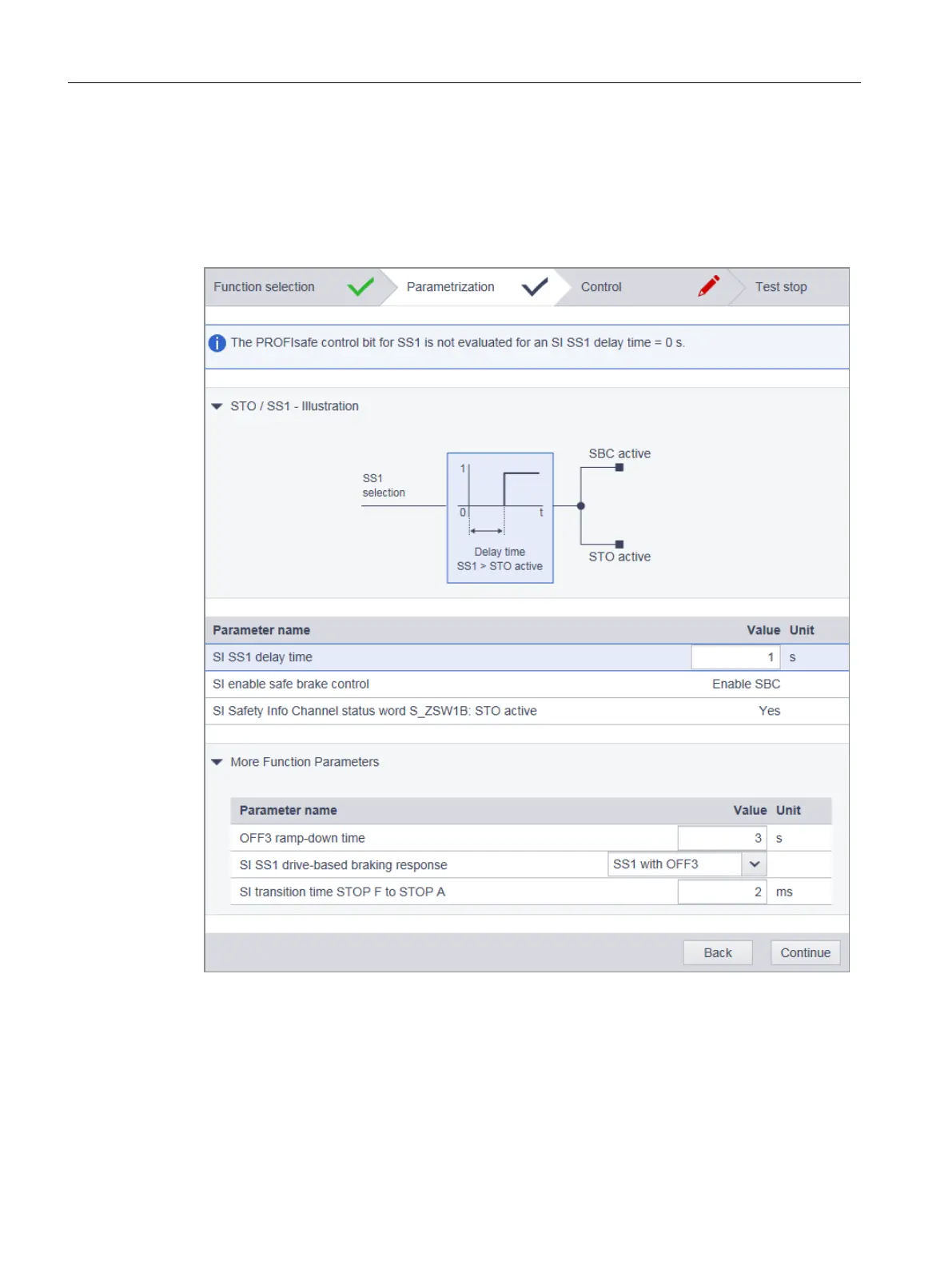 Loading...


