Requirements placed on the external braking resistor
WARNING
Risk of fire caused by continuous overload
If the external braking resistor is continuously overloaded, for example as the result of a
defective braking chopper, this can result in an explosion or fire - or the housing could melt.
● Use only braking resistors that are intrinsically safe.
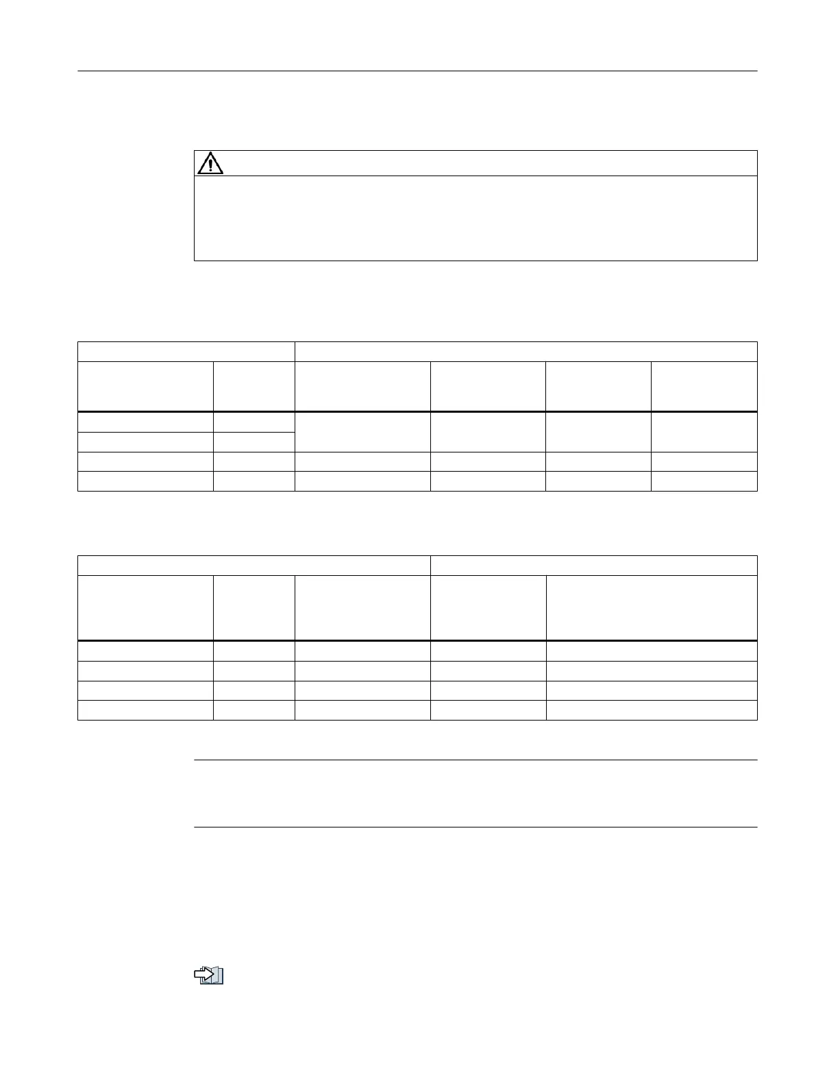
Table 3-3 Resistance data for an external braking resistor
Converter Braking resistor
Article number Power
[W]
Resistance
[Ω]
Peak braking pow‐
er
[kW]
Braking energy
[kJ]
Rated power
[W]
6SL3210-5HB10-1UF0 100
150 1.09 0.8 20
6SL3210-5HB10-2UF0 200
6SL3210-5HB10-4UF0 400 100 1.64 1.23 21
6SL3210-5HB10-8UF0 750 50 3.28 2.46 62
Table 3-4 Examples of suitable external braking resistors from a third party
Converter Braking resistor
Article number Power
[W]
Continuous braking
power of the brake
chopper
[W]
Peak braking pow‐
er
[kW]
Example of manufacturer or equiva‐
lent
6SL3210-5HB10-1UF0 100 50 1.1 Michael Koch GmbH, BWG250150
6SL3210-5HB10-2UF0 200 100 1.1 Michael Koch GmbH, BWG250150
6SL3210-5HB10-4UF0 400 200 1.7 Michael Koch GmbH, BWG500100
6SL3210-5HB10-8UF0 750 240 3.6 Michael Koch GmbH, BWG600047
1)
1) For thermal reasons, it is not permissible that the continuous braking power of 240 W is exceeded.
Note
Braking resistor with temperature monitoring
Use only a braking resistor with temperature monitoring.
Connecting the external braking resistor
Use shielded cables to connect power to the external braking resistor.
How to connect the external braking resistor and the temperature monitoring is described in
the following Sections:
Connections for open-loop and closed-loop control of the converter (Page 101).
Configuring
3.4 Configuring the external braking resistor
SINAMICS S210 servo drive system
Operating Instructions, 12/2017, A5E41702836B AA 53

 Loading...


