Commissioning Manual
122 01/2017
7-segment LED display description
Depends on current menu operation
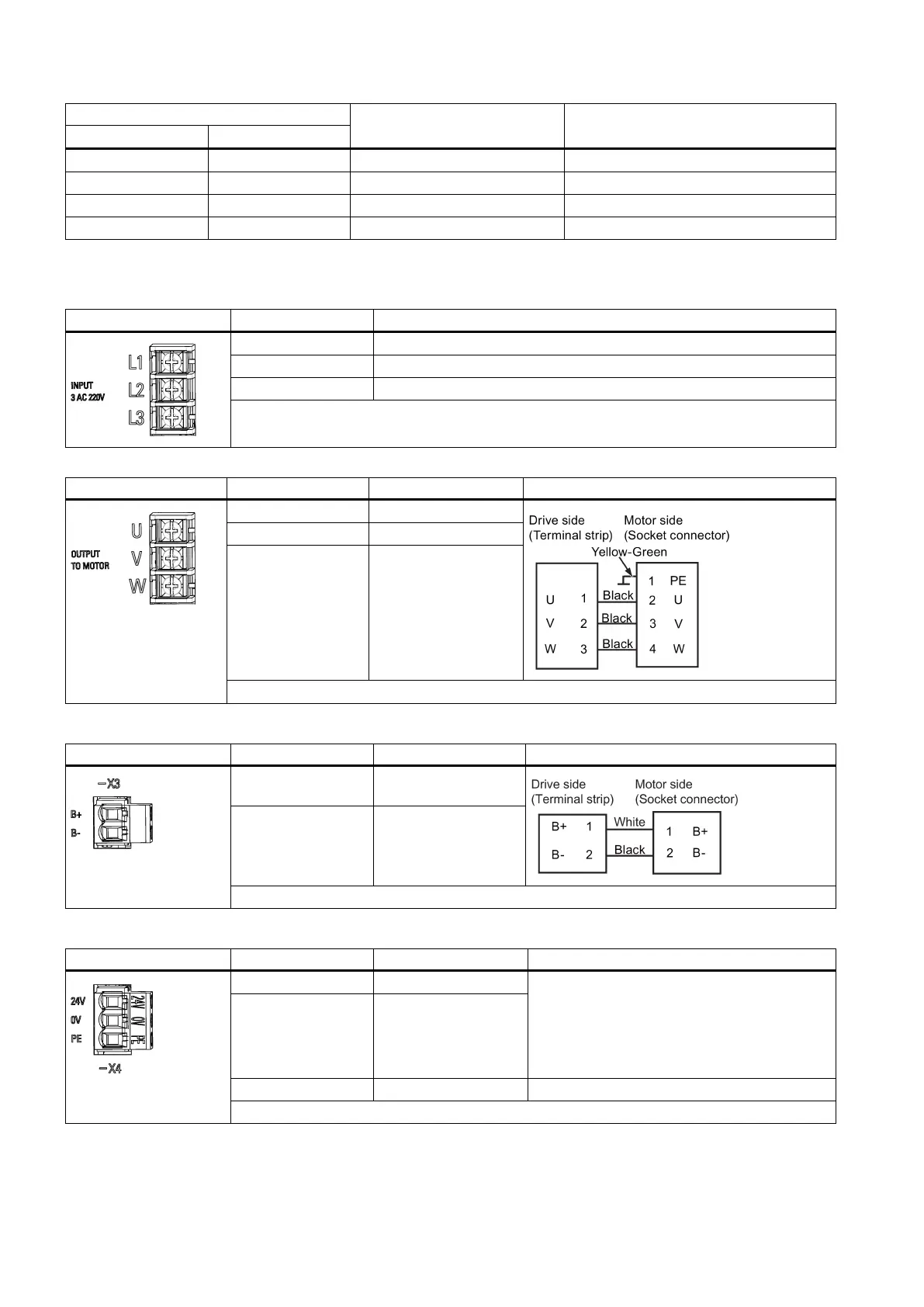
Main circuit interfaces
Main circuit interfaces - drive side
Maximum conductor cross-section: 2.5 mm
2
Main circuit interfaces - motor side
Schematic connection diagram
W Motor phase W
Maximum conductor cross-section: 2.5 mm
2
Connecting the holding brake - X3
Schematic connection diagram
B+ + 24 V, motor brake
B- 0 V, motor brake volt-
age negative
Maximum conductor cross-section: 1.5 mm
2
Connecting the 24 V power supply - X4
Voltage 24 V DC
(20.4 - 28.8 V)
Current consumption:
• Max. 0.8 A without brake power supply
•
Max. 1.4 A with brake power supply
0 V 0 V
Maximum conductor cross-section: 1.5 mm
2

 Loading...


