Commissioning Manual
01/2017
91
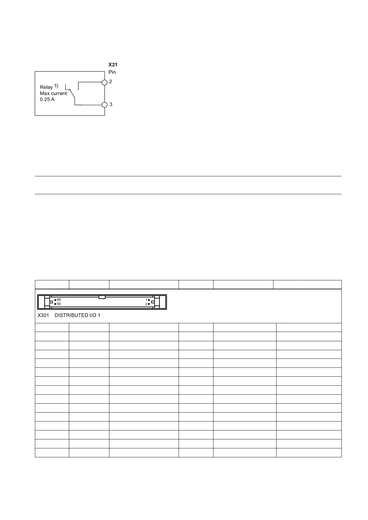
NC readiness is in the form of a relay contact (NO). It must be integrated into an EMERGENCY STOP circuit. The
connection diagram is shown as follows:
1 )
When the NC is not ready, the contact is open; otherwise, the contact is closed.
End sleeves are necessary if you use two cables per connection.
Fasten the cables to the screw terminals and plug the terminal into the interface X21.
You can buy the shielded cables from a third-party manufacturer.
ure optimum interference immunity, use only the shielded cable to connect the FAST I/O terminals (X21).
Distributed I/O - X301, X302
Pin assignment
Permissible level (including ripple)
High level: 20.4 V to 28.8 V
Rated digital output current: 250 mA
1)
15 I4.4 Digital input 40 Q3.1 Digital output

 Loading...


