Commissioning Manual
90 01/2017
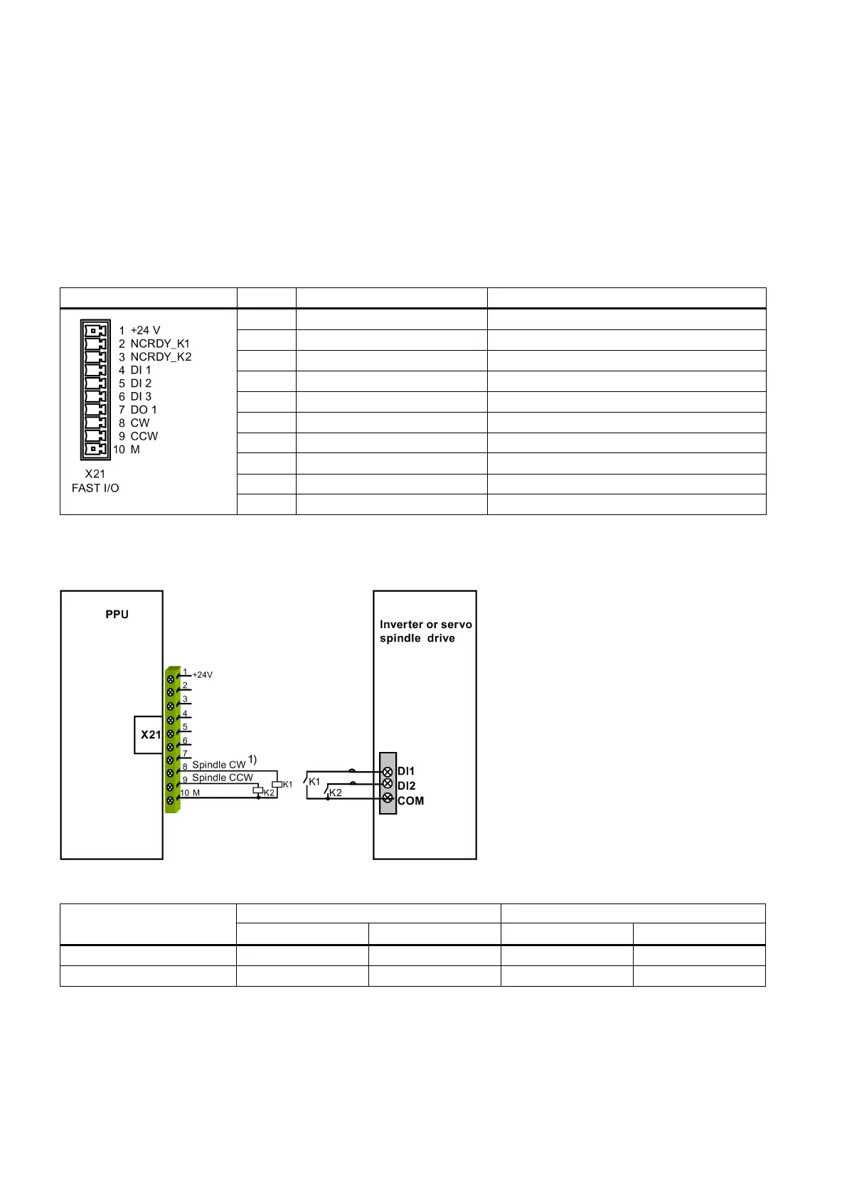
Fast input/output - X21
Pin assignment
Max. cross-section: 1.5 mm
2
(when use one cable per connection)
Permissible level (including ripple)
High level: 20.4 V to 28.8 V
+24 V input (20.4 V to 28.8 V)
NC ready signal contact 1
NC ready signal contact 2
Digital input, for connection to probe 1
Digital input, for connection to probe 2
Spindle bero or digital input
Spindle rotating clockwise
Spindle rotating counter-clockwise
You can connect the fast I/O to the inverter to control the spindle rotating direction (unipolar):
1)
See the following table for the enable status of pin 8 and pin 9 when the spindle rotates clockwise or counter-clockwise
respectively for unipolar 1 and unipolar 2.

 Loading...


