Home
Siemens
Control Unit
SINUMERIK 808D
Siemens SINUMERIK 808D Commissioning Manual
5
of 1
of 1 rating
508 pages
Give review
Manual
Specs
To Next Page
To Next Page
To Previous Page
To Previous Page
Loading...
Commissioni
ng Manual
466
01/2017
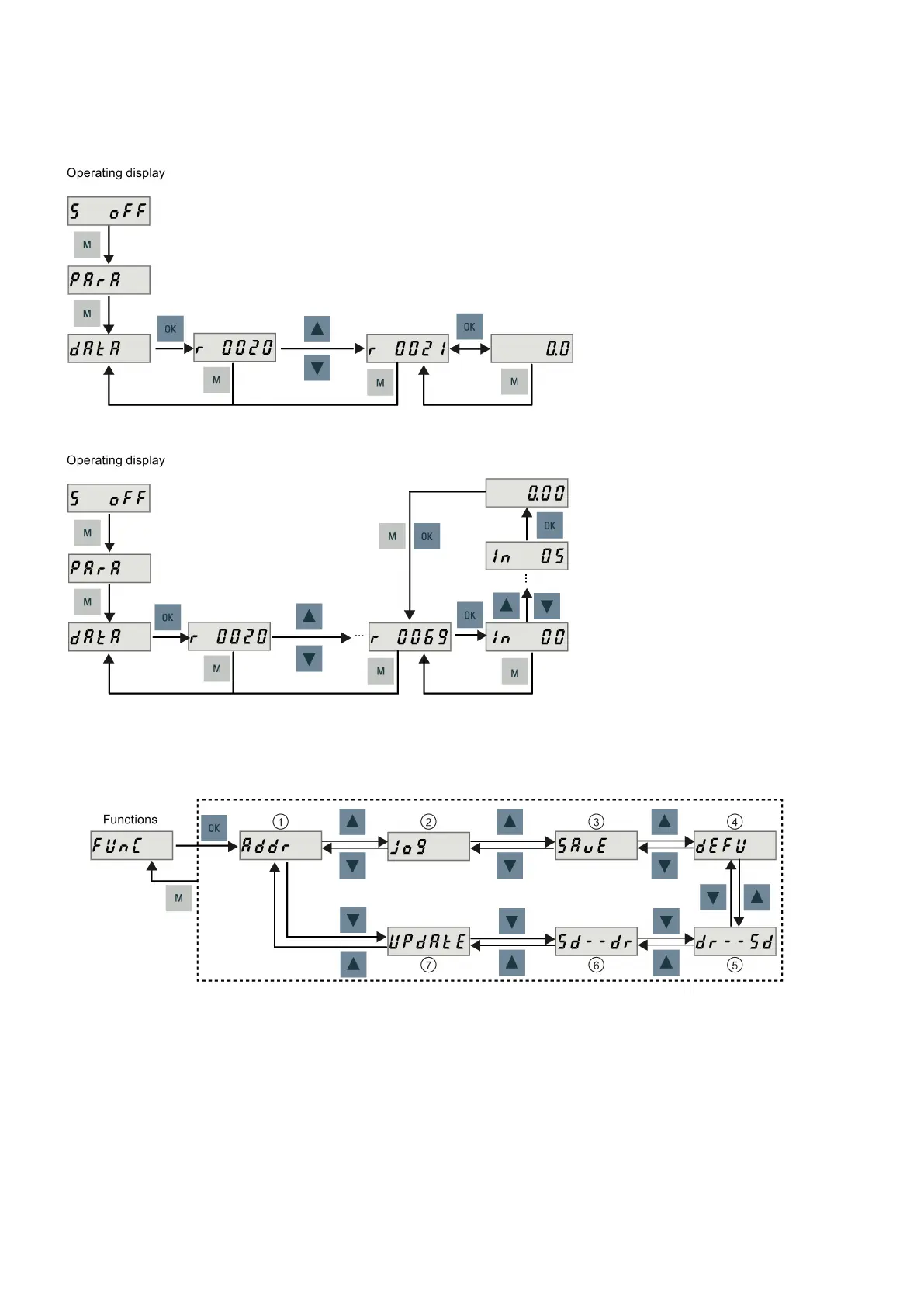
Viewing param
eters
If a parameter has no index, vi
ew its value as follows:
If a param
eter has
indices,
view its val
ue as follows:
A.1.1
.5
Auxiliary functions
Seven BOP f
unctions in total
are available:
①
Set Drive B
us addres
s
⑤
Copy param
eter set
from dri
ve to an SD
c
ard
②
Jog
⑥
Copy param
eter set
from an S
D card to dri
ve
③
Save param
eter set in
drive
⑦
Update firm
ware
④
Set paramet
er set to default
465
467
Table of Contents
Default Chapter
2
Preface
2
Table of Contents
4
1 Safety Instructions
11
Fundamental Safety Instructions
11
General Safety Instructions
11
Handling Electrostatic Sensitive Devices (ESD)
15
Industrial Security
15
Residual Risks of Power Drive Systems
16
Carrying out of Repairs
16
2 Preparation before Commissioning
17
Scope of Delivery
17
SINUMERIK 808D ADVANCED Control System
17
System Overview
17
PPU and MCP
18
Drives and Motors
20
Cables and Connectors
27
Options
29
Spare Parts
34
SINUMERIK 808D Control System
35
System Overview
35
PPU and MCP
36
Drives and Motors
36
Cables
39
Options
40
Commissioning Software Tools
41
Installing the Software Tools
41
Establishing a Connection with the Software Tools
43
Configuring the Firewall
43
Connecting with PLC Programming Tool
44
Connecting with AMM
51
Personal Computer
54
3 Mounting
55
Mounting the PPU and MCP
55
Outline Dimensions (Unit: MM)
55
Cut-Out Dimensions and Mounting Clearance
58
Mounting the PPU and MCP with the Companion Clamps
59
Mounting the Drive
61
Mounting the SINAMICS V70 Drive
61
Mounting Orientation and Clearance
61
Drill Patterns and Outline Dimensions
62
Mounting the Drive
64
Mounting the SINAMICS V60 Drive
65
Mounting Orientation and Clearance
65
Drill Patterns and Outline Dimensions
65
Mounting the Drive
66
Mounting the Motor
67
Mounting the SIMOTICS S-1FL6 Motor
67
Mounting Orientation and Outline Dimensions
67
Mounting the Motor
71
Mounting the SIMOTICS S-1FL5 Motor
72
Mounting Orientation and Outline Dimensions
72
Mounting the Motor
72
Mounting the SIMOTICS M-1PH1 Main Motor
73
Mounting Orientation and Outline Dimensions
73
Mounting the Motor
76
Electrical Cabinet Design
78
Correct Installation of Fans
78
Correct Installation of Cooling Units
79
Notes on the Laying of Cables in Drag Chains
79
4 System Connection
80
System Connection Overview
81
Interfaces on the PPU
84
Control Elements on the PPU
84
Status Leds on the PPU
85
PPU Interface Overview
86
Connecting the PPU
87
Digital Input Interfaces - X100, X101, X102
88
Digital Output Interfaces - X200, X201
89
Fast Input/Output - X21
90
Distributed I/O - X301, X302
91
Handwheel Inputs - X10
95
Drive Bus Interface - X126 (PPU161.3 and PPU160.2 Only)
96
Pulse Drive Interfaces - X51, X52, X53 (PPU141.2 Only)
97
Analog Spindle Interface - X54, Spindle Encoder Interface - X60
99
Ethernet Interface - X130
101
Power Supply Interface - X1
102
RS232 Interface - X2 (PPU160.2 Only)
102
USB Interface - X30
103
USB Interface on the Front Cover of the PPU
104
Maintenance Door/Slot for the System CF Card
104
Interfaces on the MCP
105
Control Elements on the MCP
105
MCP Interface Overview
106
Interfaces on the SINAMICS V70 Servo System
107
Status Leds on the SINAMICS V70 Drive
107
Interface Overview
108
SINAMICS V70 Feed Servo System
108
SINAMICS V70 Spindle Servo System
110
Main Circuit Interfaces
112
Connecting the 24 V Power Supply/Sto - X6
114
Connecting the Holding Brake - X7 (Feed Drive Only)
117
Connecting the Encoder - X9
118
Connecting an External Braking Resistor
121
Interfaces on the SINAMICS V60 Servo System
121
Status Leds on the SINAMICS V60 Drive
121
Main Circuit Interfaces
122
Connecting the Holding Brake - X3
122
Connecting the 24 V Power Supply - X4
122
Setpoint Interface - X5
123
Digital I/O Interface - X6
123
Connecting the Encoder - X7
124
Signal Sequence Example
125
Connecting the SINAMICS V70 Servo System
126
Connecting the Drive to Motor
126
Connecting the Terminal Boxes of the 1PH1 Motor
130
Connecting the SINAMICS V60 Servo System
132
Connecting the Drive with the SINUMERIK 808D Control System
132
Connecting the Drive with the SIMATIC PLC
134
Switching on the Drive
135
Switching on the SINAMICS V70 Drive
136
Jog Test
136
Configuring Drive Bus Addresses
138
Switching on the SINAMICS V60 Drive
139
Switching on the Control System
141
5 Initial System Setup
142
System Startup Menu
142
Synchronizing Drive Data Files between NC and Drive (PPU161.3 and PPU160.2 Only)
143
Setting the Password
144
Setting the Date and Time
146
Setting the User Interface Language
146
Changing the System Language
146
Loading System Languages
147
Activating the Optional Functions
148
6 Commissioning the PLC
150
PLC Programming Conventions
150
Signal Overview of PLC Interface
150
Operation Symbols of PLC Programming Languages
151
PLC Sample Applications
156
PLC Sample Application (Turning)
156
PLC Sample Application (Milling)
158
PLC Machine Data
160
PLC Subroutine Library
162
Overview
162
Conventions for the Symbols Used in the Subroutines
165
Subroutine 20 - AUX_MCP (Machine Auxiliary Functions)
166
Subroutine 21 - AUX_LAMP (Working Lamp)
166
Subroutine 22 - AUX_SAFE_DOOR (Safety Door)
167
Subroutine 23 - AUX_CHIP (Chip Conveyor)
168
Subroutine 24 - Aux_3Color_Lamp
169
Subroutine 31 - Plc_Ini_Usr_Ini (User Initialization)
169
Subroutine 32 - PLC_INI (PLC Initialization)
170
Subroutine 33 - EMG_STOP
170
Subroutine 37 - MCP_NCK (MCP and HMI Signal Processing)
171
Subroutine 38 - Mcp_Tool_Nr (Display Tool Number on the MCP)
173
Subroutine 39 - HANDWHL (Selecting a Handwheel According to HMI Interface Signals)
173
Subroutine 40 - AXIS_CTL (Controlling the Spindle and Axes)
174
Subroutine 41 - MINI_HHU (Handwheel on Hand-Held Unit)
176
Subroutine 42 - SPINDLE (Spindle Control)
177
Subroutine 43 - MEAS_JOG (Measurement in JOG Mode)
178
Subroutine 44 - COOLING (Cooling Control)
179
Subroutine 45 - LUBRICAT (Control of Lubricate)
180
Subroutine 46 - PI_SERVICE
181
Subroutine 47 - Plc_Select_Pp (PLC Selects a Subroutine)
183
Subroutine 48 - Servplan (Service Planner)
183
Subroutine 49 - Gearchg1_Auto (Automatic Spindle Gear Change)
184
Subroutine 50 - Gearchg2_Virtual (Virtual Spindle Gear Change)
185
Subroutine 51 - Turret1_Hed_T (Turret with Hall Effect Device Position Sensor)
186
Subroutine 52 - Turret2_Bin_T (Turret with Binary Coding Function)
188
Subroutine 53 - Turret3_Code_T (Tool Change Control for Turret with Coding Function)
190
Subroutine 54 - Turret2_3_Tooldir (Tool Change Direction)
192
Subroutine 55 - Tail_Stock_T (Tailstock Control Program for Turning Machines)
193
Subroutine 56 - Lock_Unlock_T (Clamping Control for Turning Machine)
194
Subroutine 58 (MM_MAIN)
195
Subroutine 59 (MM_MCP_808D)
197
Subroutine 60 - Disk_Mgz_M (Disk-Style Tool Magazine Used for Milling)
198
Subroutine 62 - Trg_Key_Or
200
Subroutine 63 - TOGGLES
204
Subroutines 0 to 19, 34 to 36, 57, and 61
204
PLC Programming Tool
205
Overview of PLC Programming Tool
205
Renaming the Default Program
206
Changing the Display Language
207
Selecting a Target System
208
Downloading/Uploading/Comparing PLC Applications
209
Compiling and Monitoring Programs
217
PLC Alarms
218
Alarm Cancel/Reset and Reaction
220
Editing PLC Alarm Texts
220
PLC Diagnostics
223
Handwheel Assignment
226
7 Commissioning the Prototype Machine
227
Overview on Commissioning and Operation Wizards
227
Commissioning the PLC
229
Setting PLC Related Parameters
229
Downloading and Commissioning PLC Programs
230
Checking I/O Address Assignment
231
Editing PLC Alarm Texts
231
Configuring the Drives (PPU161.3 and PPU160.2 Only)
232
Setting Basic Parameters
235
Setting Feed Axis Parameters
235
Commissioning the Referencing Function
236
Setting Spindle Parameters
238
Creating Series Archives
239
Setting Compensation Data
240
Setting Software Limit Switch Data
240
Setting Backlash Compensation Data
241
Setting Leadscrew Error Compensation Data
242
Tuning Drive Performance (PPU161.3 and PPU160.2 Only)
243
Creating Prototype Machine Commissioning Archives
246
8 Commissioning the Turret/Magazine
248
PLC Subroutines for Tool Change
248
Calling Cycles for Tool Change
248
9 Series Machine Commissioning
249
Loading Series Commissioning Archives
249
Setting Software Limit Switch Data
250
Setting Backlash Compensation Data
250
Setting Leadscrew Error Compensation Data
250
Tuning Drive Performance (PPU161.3 and PPU160.2 Only)
250
Creating Startup Archives
250
10 Network Functions
251
Network Configuration
251
Configuring the Network Drive
252
Configuring the Firewall
254
11 Measurement Functions
255
Fast Inputs and Outputs
255
Probe Commissioning
256
12 Extended Drive Commissioning
257
Configuring the Additional Axis
257
Configuring the Additional Axis for SINUMERIK 808D ADVANCED Control System
257
Configuring an Additional Feed Axis
257
Configuring an Additional Spindle
260
Configuring the Additional Axis for SINUMERIK 808D Control System
264
Configuring the y Axis on a Turning Machine
265
Setting Parameters for the y Axis
265
Measuring the Tool Manually (with the y Axis)
266
13 Other Frequently Used Functions
270
Playing a Slide Show
270
Defining the Service Planner
272
Using the Machine Manufacturer's Startup Screen and Machine Logo
273
Creating User Cycles
277
Creating the User Cycle File
277
Creating the User Cycle Alarm File
279
Creating the User Cycle Bitmap File
279
Creating the Extended User Text File
279
Creating the User Cycle Softkey Index File
280
Creating the User Cycle Parameter File
280
Transferring the Desired Files to the Control System
281
Calling the Created User Cycle
284
Using the Machine Manufacturer's Machine Data Descriptions
286
Using the Machine Manufacturer's R Variable Names
287
PI Service Functions
288
CNC Lock Function
289
Function Overview
289
Creating the Activation File
291
Importing the Activation File
292
Extending the CNC Lock Function
293
Deactivating the CNC Lock Function
294
OEM PIN Forgotten
296
Other Information
296
14 Customizing HMI Display with Easyxlanguage Scripts
298
Scope of Functions
298
Fundamentals of Configuration
299
Configuration Files (Easyxlanguage Scripts)
300
Structure of Configuration File
301
Language Dependency
302
Creating Language-Dependent Texts
302
XML Identifier
302
General Structure
302
Instruction/Identifier Description
303
System Variables
323
Color Coding
323
Special XML Syntax
323
Operators
324
Generating Softkey Menus and Dialog Forms
324
Generating User Menus
349
Creating Processing Cycle Forms
349
Substitution Characters
352
Addressing Components
352
PLC Addressing
352
Addressing NC Variables
353
Generating NC/PLC Addresses During the Runtime
353
Addressing Drive Components
353
Addressing Machine and Setting Data
354
Addressing the User Data
355
Predefined Functions
355
15 Technical Data
383
Sinumerik 808D/Sinumerik 808D Advanced
383
Servo Drives
384
SINAMICS V70 Feed Drives
384
SINAMICS V70 Spindle Drives
386
SINAMICS V60 Servo Drives
388
Servo Motors
390
SIMOTICS S-1FL6 Feed Motors
390
SIMOTICS S-1FL5 Servo Motors
394
SIMOTICS M-1PH1 Main Motors
396
Cables
408
Drive Bus Cable for the SINUMERIK 808D ADVANCED
408
Cables for the SINAMICS V70 Servo System
408
Cables for the SINAMICS V60 Servo System
409
Transformers for the SINAMICS V60 Servo System
410
Address of CE-Authorized Manufacturer
411
16 Parameter List
411
Basic Machine Data
411
SINAMICS V70 Parameters
416
V70 Parameters on BOP
418
Drive Basic List on HMI
425
SINAMICS V60 Parameters
427
17 PLC User Interface
431
Signals From/To the MCP
431
Reading/Writing NC Data
433
Reading/Writing NC Data: Job
433
Reading/Writing NC Data: Result
433
PI Service
434
PI Service: Job
434
PI Service: Result
434
Retentive Data Area
434
User Alarms
435
User Alarms: Activating
435
Variables for User Alarms
435
Active Alarm Response
436
Alarm Acknowledgement
436
Signals From/To HMI
436
Program Control Signals from the HMI (Retentive Area)
436
Program Selection from PLC (Retentive Area)
437
Checkback Signal: Program Selection from HMI (Retentive Area)
437
Signals from HMI
437
Signals from PLC
437
Signals to Maintenance Planners
438
Signals from Maintenance Planners
438
Signals from Operator Panel (Retentive Area)
439
General Selection/Status Signals from HMI (Retentive Area)
439
General Selection/Status Signals to HMI (Retentive Area)
439
Auxiliary Functions Transfer from NC Channel
440
Overview
440
Decoded M Signals (M0 to M99)
441
Transferred T Functions
441
Transferred M Functions
441
Transferred S Functions
442
Transferred D Functions
442
Transferred H Functions
442
NCK Signals
442
General Signals to NCK
442
General Signals from NCK
443
Signals at Fast Inputs and Outputs
443
Signals from Fast Inputs and Outputs
444
Channel Signals
445
Signals to NC Channel
445
Signals from NC Channel
447
Axis/Spindle Signals
450
Transferred M and S Functions, Axis Specific
450
Signals to Axis/Spindle
450
Signals from Axis/Spindle
453
PLC Machine Data
455
INT Values (MD 14510 USER_DATA_INT)
455
HEX Values (MD 14512 USER_DATA_HEX)
455
FLOAT Values (MD 14514 USER_DATA_FLOAT)
455
User Alarm: Configuring (MD 14516 USER_DATA_PLC_ALARM)
456
Signals, Synchronized Actions
456
Signals, Synchronized Actions to Channel
456
Signals, Synchronized Actions from Channel
456
Reading and Writing PLC Variables
456
Axis Actual Values and Distance-To-Go
457
Maintenance Scheduler: User Interface
457
Initial (Start) Data
457
Actual Data
457
User Interface for Ctrl Energy
458
A Appendix
459
Operation and Display
459
Operating the SINAMICS V70 Basic Operator Panel (BOP)
459
BOP Overview
459
A.1 Operation and Display
459
Parameter Structure
463
A.1.1.2 Parameter Structure
463
Actual Status Display
464
Basic Operations
464
Auxiliary Functions
466
A.1.1.5 Auxiliary Functions
466
Operating the SINAMICS V60 Basic Operator Panel (BOP)
471
BOP Overview
471
Main Menu
471
Function Menu
473
A.1.2.3 Function Menu
473
Parameter Setting Menu
475
Data Display Menu
476
Setpoints from the PPU
476
Replacing the Fan for the V70 Drive
477
Replacing the Fan for the 1PH1 Motor
480
Assembling the Power Cable for the 1PH1 Motor
480
Assembling the Line Supply Terminal for the Drive
483
Cutting Reserved Holes in the MCP
483
Customizing Pre-Defined Labeling Strips for Keys of the MCP
484
Diagnostics
485
SINUMERIK 808D/SINUMERIK 808D ADVANCED Alarms
485
A.8 Diagnostics
485
SINAMICS V70 Faults and Alarms
486
General Information about Faults and Alarms
486
List of Faults and Alarms
487
SINAMICS V60 Faults and Alarms
499
Overview
499
Common Faults and Alarms
499
Errors During Drive Self-Test
502
Other Faults
502
AMM Communication Tool
503
File Management and Transfer
503
Remote Control
505
Configuring the Remote Control
505
A.9.2 Remote Control
505
Other manuals for Siemens SINUMERIK 808D
Service Manual
48 pages
Function Manual
331 pages
User Manual
339 pages
Programming And Operating Manual
208 pages
Parameter Manual
524 pages
Installation Manual
48 pages
Operating Instructions
86 pages
Service Guide
46 pages
Operating Guide
114 pages
5
Based on 1 rating
Ask a question
Give review
Questions and Answers:
Need help?
Do you have a question about the Siemens SINUMERIK 808D and is the answer not in the manual?
Ask a question
Siemens SINUMERIK 808D Specifications
General
Brand
Siemens
Model
SINUMERIK 808D
Category
Control Unit
Language
English
Related product manuals
Siemens SINUMERIK 808D ADVANCED
498 pages
SINUMERIK 808D ADVANCED Series
480 pages
Siemens SINUMERIK 802D
399 pages
Siemens SINUMERIK 880
291 pages
Siemens SINUMERIK 810D
520 pages
Siemens SINUMERIK 840D
713 pages
Siemens SINUMERIK 840C
291 pages
Siemens SINUMERIK 840Di
552 pages
Siemens Sinumerik 840 sl
520 pages
Siemens SINUMERIK 840Di sl
470 pages
Siemens Sinumerik 840DiE sl
545 pages
SINUMERIK 840D Simodrive 611 digital
298 pages

 Loading...


