Commissioning Manual
174 01/2017
Subroutine 40 - AXIS_CTL (controlling the spindle and axes)
Purpose
Subroutine 40 is used to control the drive pulse enable (DB380x.DBX4001.7) and controller enable (DB380x.DBX2.1),
monitoring the hardware limits and the reference cam signals, and controlling the enable signal for the spindle according to a
spindle command (for example, SPINDLE CW, SPINDLE CCW, M03, M04, SPOS, etc.). The motor brake is automatically
controlled by the SINAMICS V70 drives.
This subroutine provides two ways to realize the hardware limit control:
● PLC solution (MD14512 [18] bit 6 = 0)
Each feed axis has one (MD14512 [18] bit 7 = 1) or two (MD14512 [18] bit 7 = 0) hardware limit switches. This
subroutine activates the NCK hardware limit function via the NCK interface DB380x.DBX1000.0 or DB380x.DBX1000.1
according to the configurations of the hardware limit switches, and thus makes the NCK produce a feed stop signal to an
over-distance axis.
Furthermore, you can also connect the output
of this subroutine with the input
of subroutine 33 to
activate the Emergency Stop automatically once the hardware limit of any axis has been reached.
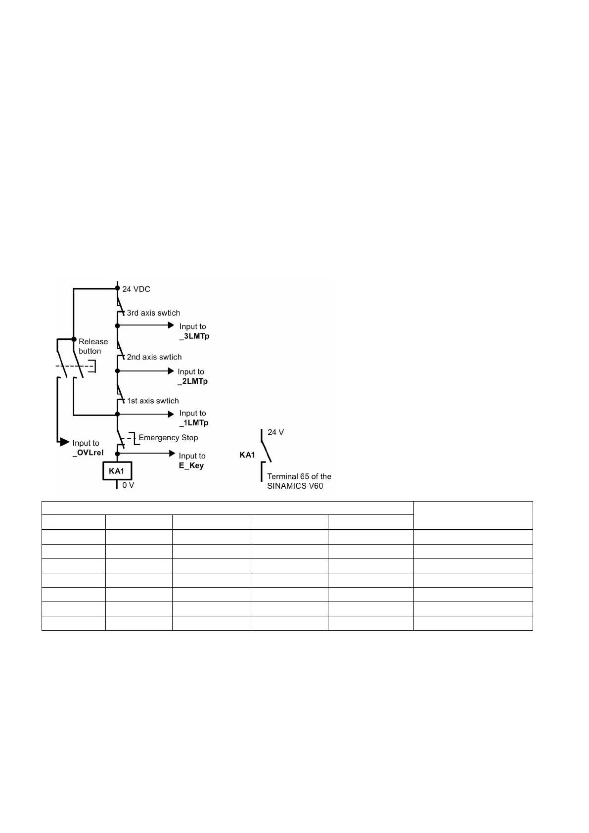
● Hardware solution (MD14512 [18] bit 6 = 1)
This solution is independent of the PLC and thus is much safer:
Encoding the hardware limit switches
0 0 0 1 DB3901.DBX4.6 2nd - over limit
In the hardware solution above, the feed stop signals for all axes can be activated via the hardware limit switches when any
of the hardware limits is reached or an EMERGENCY STOP happens. You can check the information of the PLC diagnostics
from the encoding of the hardware limit switches shown in the table above, and identify the cause (Emergency Stop button
or a hardware limit switch of an axis) of the EMERGENCY STOP signal.

 Loading...


